Control Valve Diagram
Control valve A valve which controls the flow rate or flow direction in a fluid system The final control element, through which a fluid passes, that adjusts the flow passage as directed by a signal from a controller to modify the flow rate.

Control valve diagram. Valves ending in SH uses LSRK, valve ending in SHA uses LSJRSHK, valve ending in HHA uses LSJRHHK There are also a number of different kits available for this valve depending on the spool action, and handle option the valve is equipped with Please contact factory for specific kit numbers relating to different spool actions, and handle options. Once this has been completed, the power steering control valve should easily come off Step 12 Install the new control valve Once the old valve has been removed, installing the new control valve is simply done in reverse of the installation Screw the control valve onto the control arm drive link and bolt the control valve to the pitman arm. SV Stack Valve Parts Manual Covers model numbers starting with SVE, SVG, SVI, SVH, SVL, SVM, SVR and SVS;.
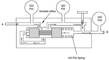
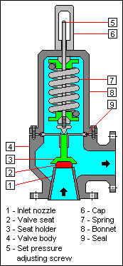
The reason why a pneumatic control valve’s stem position corresponds linearly to the amount of air pressure applied to the actuator is because mechanical springs tend to follow Hooke’s Law, where the amount of spring motion (\(x\)) is directly proportional to applied force (\(F = kx\))A pneumatic actuator applies force as a function of air pressure and piston/diaphragm area (\(F = PA. Tl4b l control valve TL4B L CONTROL VALVE (NEW TYPE) COMPONENT PARTS TL421 (FRT. ORI – The ORI head pressure control valve is an inlet pressure regulating valve and responds to changes in condensing pressure only The valve designation stands for on Rise of Inlet pressure As shown in Figure 5, the outlet pressure is exerted on the underside of the bellows and on top of the seat disc.
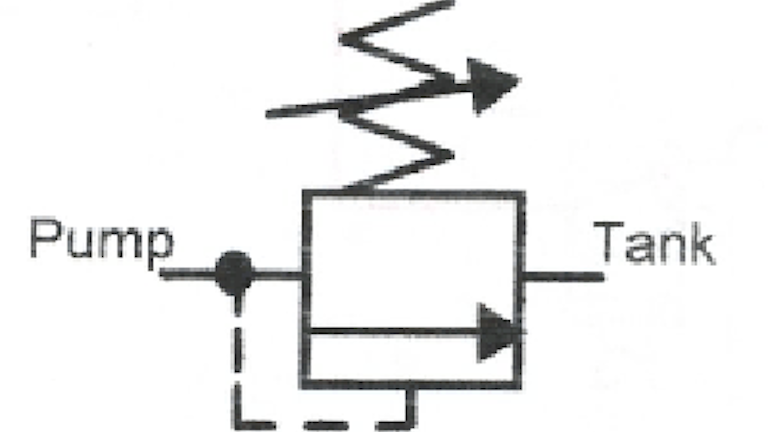
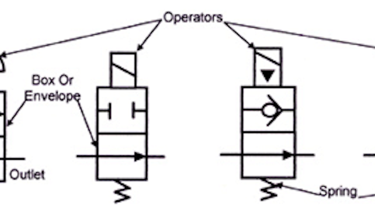
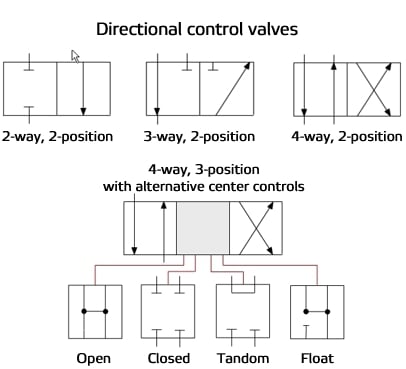
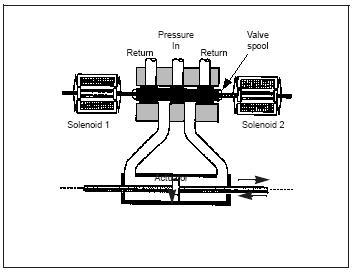
Control valve and instrumentation terminology Chapter 2 develops the vital topic of control valve performance Chapter 3 covers valve and actuator types Chapter 4 describes digital valve controllers, analog positioners, boosters, and other control valve accessories Chapter 5 is a comprehensive guide to selecting the best control valve for an. Proportional valves, on the other hand, control direction and speed In addition to shifting into discrete positions, they can shift into intermediate positions to control actuator direction, speed, acceleration, and deceleration Even more basic than the discrete directionalcontrol valve is the binary valve. Directional air control valves are the building blocks of pneumatic control Pneumatic circuit symbols representing these valves provide detailed information about the valve they represent Symbols show the methods of actuation, the number of positions, the flow paths and the number of ports Here is a brief breakdown of how to read a symbol.
Trim Set the control valve (Trim Control Valve) is the word of Plug Stem Seat Ring, which collectively set trim (trim set) itself Positioner or position will be the key to control of the control valve The industry standard device that converts the signal (signal standard), such as 4 mA, 315 psi as wind power to propel Actuator head movements. Cross valves feature products with a long dependable service life and optimum versatility due to many standard and optional features Cross offers directional control valves, single and double selector valves and inline relief valves. ORI – The ORI head pressure control valve is an inlet pressure regulating valve and responds to changes in condensing pressure only The valve designation stands for on Rise of Inlet pressure As shown in Figure 5, the outlet pressure is exerted on the underside of the bellows and on top of the seat disc.
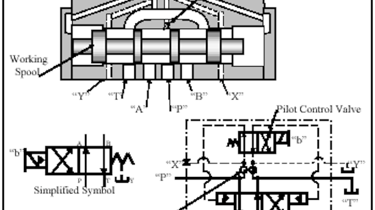
Shop by Department Order by browsing parts Car Hauler Trailer Parts Car Hauler Trailer Parts Gear Heads & Locks (8) Position Safety Locks (3) Pumps & Motors (18) Cylinders & Control Valve Hardware (135) Batwing & Flipper Hardware (2). Directional air control valves are the building blocks of pneumatic control Pneumatic circuit symbols representing these valves provide detailed information about the valve they represent Symbols show the methods of actuation, the number of positions, the flow paths and the number of ports Here is a brief breakdown of how to read a symbol. Hopefully, you can already begin to see how some of these components will work together like how a directional control valve will control a cylinder 4 Identify the flow path at a deenergized state As I mentioned, looking for the pump(s) in a schematic is where I start Trace lines outward from the pump until you hit a closed valve.
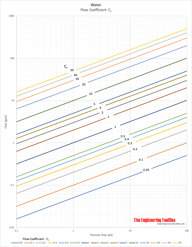
Customer Pickup Orders to help reduce exposure for our customers and our employees, if you are placing an order for instore pickup please call in your order ahead of time or place your order online and prepay with a credit card Be sure to let us know when you plan to arrive We will have your merchandise ready for you and will greet you outside our facility. Example Required C v for a water control valve With water flow 6 gpm and designed pressure drop 10 psi through a control valve the required flow coefficient C v can be estimated to ~ 2 as indicated in the chart below. Control valves, serving waterworks, fire protection, aviation ground fueling, marine and industrial customers throughout the world Our commitment to excellence and continuous improvement shows in each valve we produce and in the many new products we introduce to the marketplace each year.
0A Kit to convert 0C open center valve to 0C closed center valve 08 lbs $4030. LS3000, RD2500, DS And SS Parts Manual Covers models starting with LS3000, RD2500, DS and SS;. CHEVROLET CONTROL VALVE INSTALLATION REFER TO THE DIAGRAM ON THE BACK OF THIS PAGE 1 Raise the front of the vehicle off the floor and place on stands 2 Install rebuilt control valve onto center link, turning approximately 2123 turns For correct position, measure distance between driver side inner tie rod stud and valve stud.
The idle air control valve — also known as the "idle speed control valve" — regulates the idle speed of your engine This is controlled by the engine's computer Sometimes parts go bad, which results in your car idling strangely or stalling Check to see if your idle control valve is functioning properly before attempting to replace it. Complete control valve (3400 psi w/handle assy) # ;. Control valves and cavitation, application ratio and multi stage control valves FailClosed A control valve that goes to closed position if control signal or air fails FailLast A control valve that should stay put if control signal or air fails FailOpen A control valve that goes to open position if control signal or air fails.
Trim Set the control valve (Trim Control Valve) is the word of Plug Stem Seat Ring, which collectively set trim (trim set) itself Positioner or position will be the key to control of the control valve The industry standard device that converts the signal (signal standard), such as 4 mA, 315 psi as wind power to propel Actuator head movements. Shop by Parts Schematics Order direct from a parts diagram;. 0A Kit to convert 0C open center valve to 0C closed center valve 08 lbs $4030.
NOTE The Valve is to be replaced during the Warranty period, not repaired or disassembled Disassembly of the Valve will void Warranty Note The lever bracket # is the most common service part on these valves Periodically check that the mounting screws are not loose. RD4100 Parts Manual Covers model numbers starting with RD41. Because Velvac valves are multipurpose we can also control double acting air cylinders (air to open air to close) if required using the same valve but as a 4 way function • Solenoid or “Electric Over Air” Valves Many of the circuits shown here use solenoid operated valves as well as air pilot operated valves and a few manual valve.
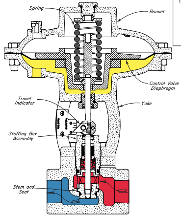
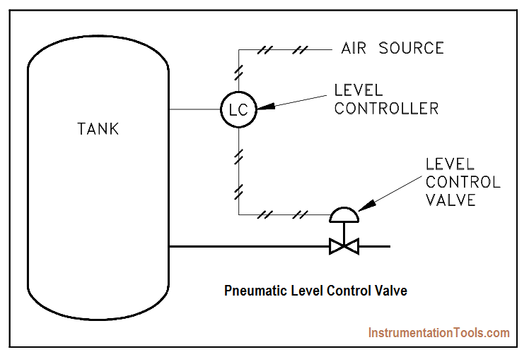
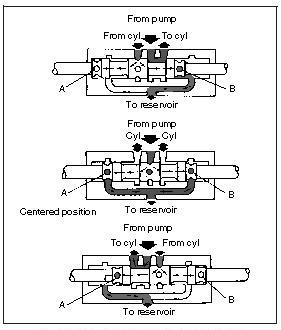
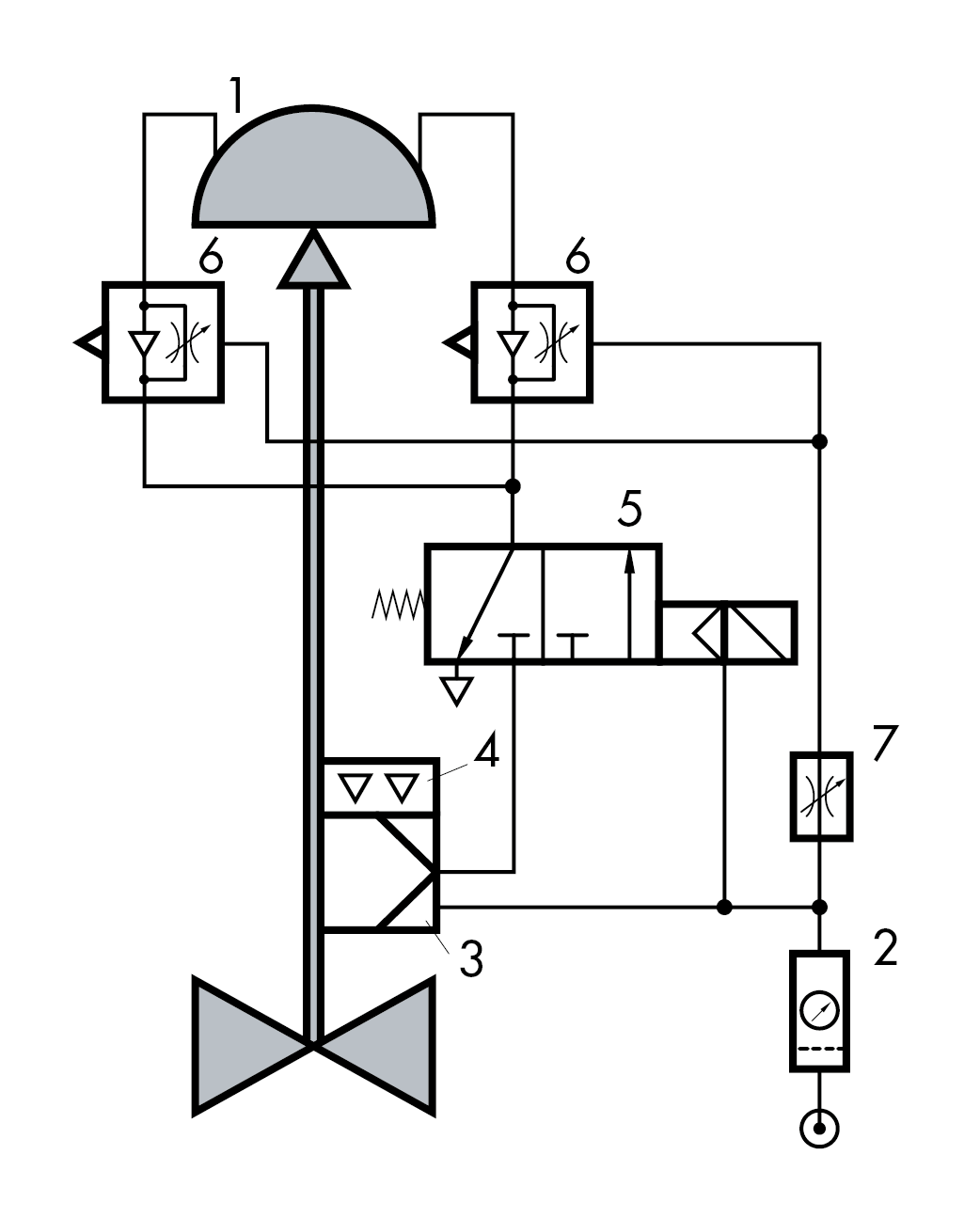
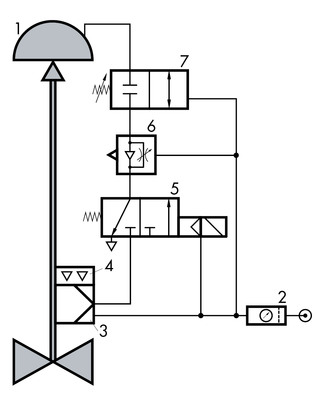
Control valves are valves used to control conditions such as flow, pressure, temperature, and liquid level by fully or partially opening or closing in response to signals received from controllers that compare a “setpoint” to a “process variable” whose value is provided by sensors that monitor changes in such conditions Control Valve is also termed as the Final Control Element. The diagram above is for a linear sliding stem control valve without a positioner The valve has an actuator bench set of 5 – 13psig As can be seen, the valve configuration is air to open, fail close (ATO –FC). Series Stack Valve Parts Manual Covers model numbers starting with E, I, L, P, T, and U;.
Fleck 5600 control valve parts, electronic turbine meter assembly, day timer powerhead, injector assembly, brine seal and spacer kit for fleck 5600 control valve Click on the diagram images below to buy the products by part number Control Valves Drive Assembly Econominder Drive Assembly Bypass Assembly Plastic 2300 Safety Brine. Ref No Part No NO Req Description Ship Weight Price (USD) 0C 1 Log Splitter Valve, 4way tandem center with relief valve, detent hold with hydraulic kickout in "A" and Spring centered to neutral from "B". The diagram above is for a linear sliding stem control valve with a positioner The valve has an actuator bench set of 5 – 13psig As can be seen, the valve configuration is air to open, fail close (ATO –FC).
Valves ending in SH uses LSRK, valve ending in SHA uses LSJRSHK, valve ending in HHA uses LSJRHHK There are also a number of different kits available for this valve depending on the spool action, and handle option the valve is equipped with Please contact factory for specific kit numbers relating to different spool actions, and handle options. This is a very simple animated illustration on the basics of hydraulic schematic symbols In this topic we are talking about how the hydraulic schematic symb. Example Required C v for a water control valve With water flow 6 gpm and designed pressure drop 10 psi through a control valve the required flow coefficient C v can be estimated to ~ 2 as indicated in the chart below.
SV Stack Valve Parts Manual Covers model numbers starting with SVE, SVG, SVI, SVH, SVL, SVM, SVR and SVS;. NOTE The Valve is to be replaced during the Warranty period, not repaired or disassembled Disassembly of the Valve will void Warranty Note The lever bracket # is the most common service part on these valves Periodically check that the mounting screws are not loose. The simplest DCV (Direction Control Valve ) is a check valve A check valve allows flow in one direction, but blocks the flow in the opposite direction It is a twoway valve because it contains two ports Figure shows the graphical symbol of a check valve along with its noflow and freeflow directions Symbol Of Check Valve.
Control valve A valve which controls the flow rate or flow direction in a fluid system The final control element, through which a fluid passes, that adjusts the flow passage as directed by a signal from a controller to modify the flow rate. Usually, endocarditis is due to a serious infection of the heart valves Mitral valve prolapse The mitral valve is forced backward slightly after blood has passed through the valve. RD4100 Parts Manual Covers model numbers starting with RD41.
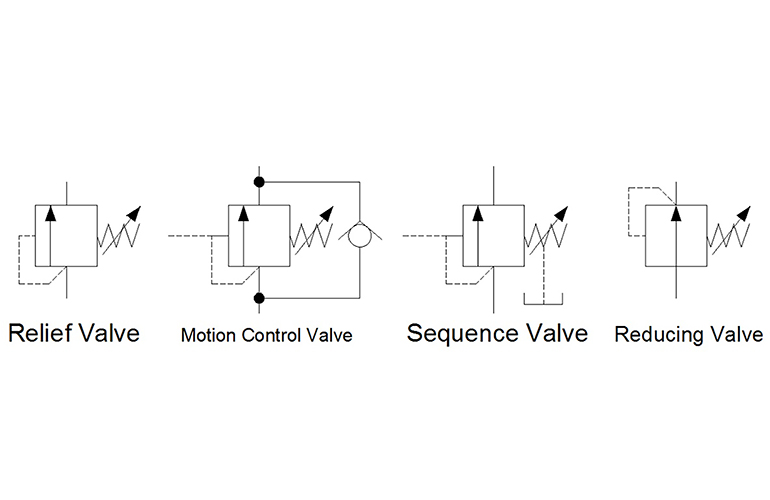
There are two types of valves, directional control valves and pressure relief valves Directional control valves manage the flow path of the fluid in the system Pressure relief valves protect the system plumbing and components against pressure overloads They also limit the output force exerted by rotary motors and cylinders. An oil control valve (also referred to as a VVT solenoid) is an important component of a vehicle with a variable valve timing (VVT) system The existence of the system aims to control the performance of the engine utilizing two methods to retard and advance camshaft angle. LS3000, RD2500, DS And SS Parts Manual Covers models starting with LS3000, RD2500, DS and SS;.
Height Control Valve 2 Height Control Valves Height Control Valves Trailer air suspension systems require precise air flow management Using an Advanced ShearSeal® design to ensure accurate air flow, Hendrickson Height Control Valves (HCV) deliver superior performance and durability. Complete control valve (3400 psi w/handle assy) # ;. A control valve is a valve used to control fluid flow by varying the size of the flow passage as directed by a signal from a controller This enables the direct control of flow rate and the consequential control of process quantities such as pressure, temperature, and liquid level In automatic control terminology, a control valve is termed a "final control element".
NOTE The Valve is to be replaced during the Warranty period, not repaired or disassembled Disassembly of the Valve will void Warranty Note The lever bracket # is the most common service part on these valves Periodically check that the mounting screws are not loose. Proportional valves, on the other hand, control direction and speed In addition to shifting into discrete positions, they can shift into intermediate positions to control actuator direction, speed, acceleration, and deceleration Even more basic than the discrete directionalcontrol valve is the binary valve. Directional air control valves are the building blocks of pneumatic control Pneumatic circuit symbols representing these valves provide detailed information about the valve they represent Symbols show the methods of actuation, the number of positions, the flow paths and the number of ports Here is a brief breakdown of how to read a symbol.
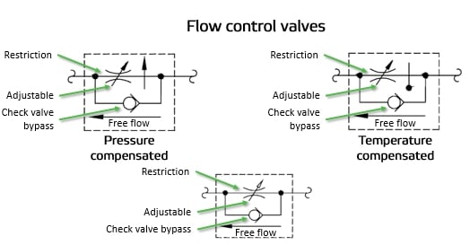
Flow control valves are used to regulate the flow rate and pressure of liquids or gases through a pipeline Flow control valves are essential for optimizing system performance, relying on a flow passage or port with a variable flow area Here’s a look at the function of hydraulic flow control valves, the various types and How Does a Hydraulic Flow Control Valve Work?. Control valves and cavitation, application ratio and multi stage control valves FailClosed A control valve that goes to closed position if control signal or air fails FailLast A control valve that should stay put if control signal or air fails FailOpen A control valve that goes to open position if control signal or air fails. Series Stack Valve Parts Manual Covers model numbers starting with E, I, L, P, T, and U;.
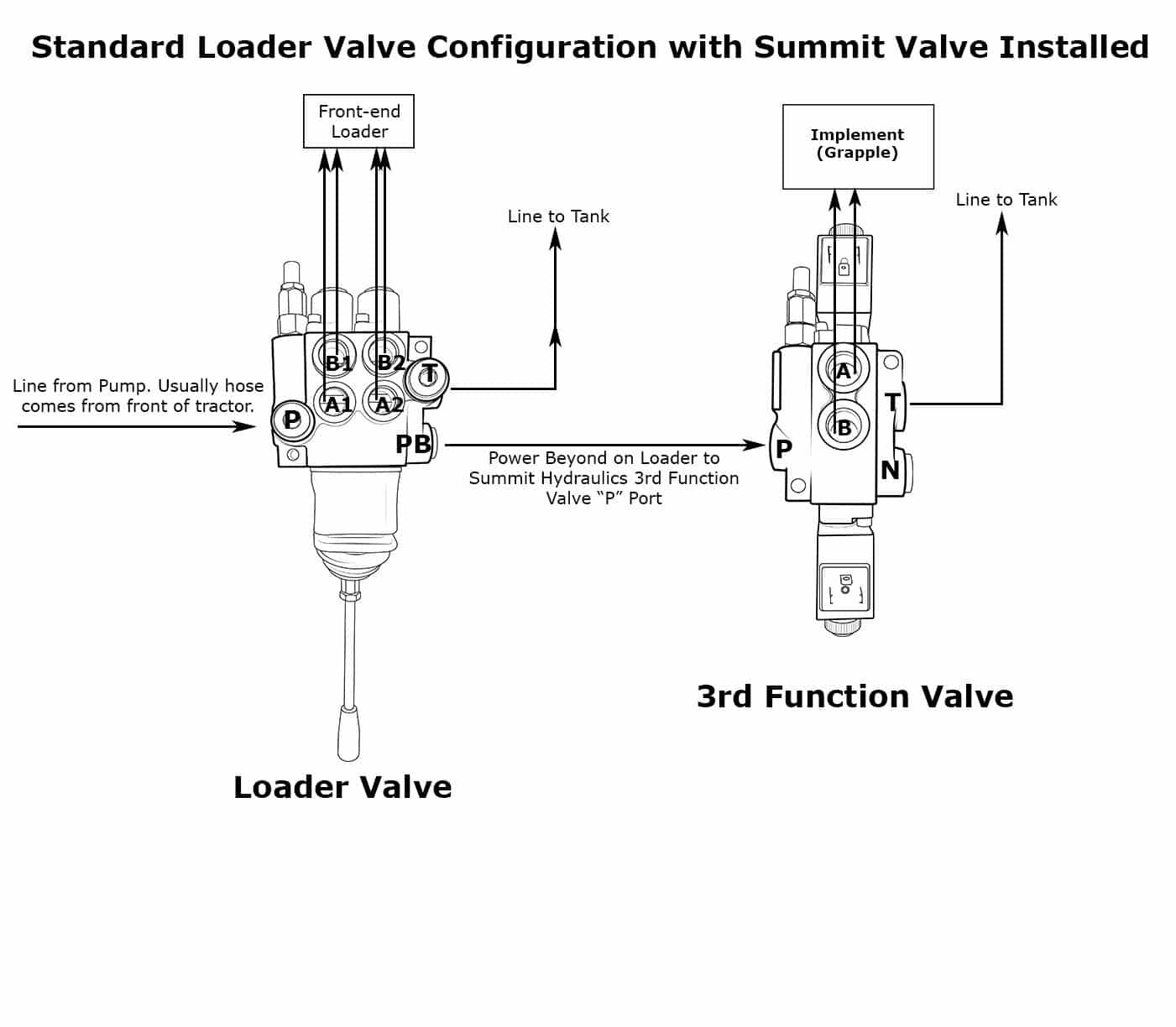
Directional Control Valves The direction that fluid flows in a line can be controlled by using valves which allow flow in only one direction These valves are typically referred to as Òcheck valvesÓ because they ÒcheckÓ the flow if it tries to reverse These valves can have simple check balls or can have machined poppet type valves. Anatomy Of Coronary Valves Diagram The aortic valve has also been called the left semilunar valve and the left coronary ostium is found midway between the commissures of the left coronary cusp, and almost immediately branches into the anterior Coronary circulation is the circulation of blood in the blood vessels that supply the heart muscle. 1) Removal of Old Power Steering Control Valve a) Raise vehicle and support it on stands so that front wheels can be turned from a full left to a full right turn b) Disconnect the 2 fluid line fittings at the control valve and drain the fluid from the lines Turn the front wheels to the left and to the right several time to force all the dirty.
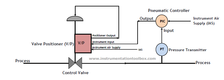
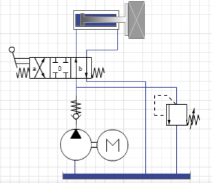
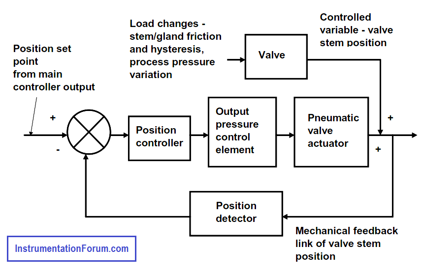
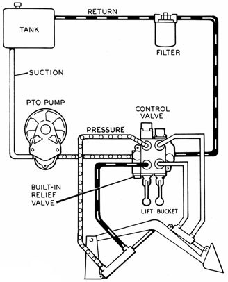
The diagram shows a winch powered by a hydraulic motor The directional control valve with builtin relief features optional flow control to control the speed of the winch The hydraulic pump and motor must be matched to the torque requirements of the winch. Control Valve Arrangement The image below shows how a control valve can be used to control rate of flow in a line The "controller" receives the pressure signals, compares them with pressure drop for the desired flow and if the actual flow is different, adjusts the control valve to increase or decrease the flow. Directional valves route the flow of fluid into ports A and B based on the application In this howto repair video, we'll be discussing several topics inc.
PTP 3Way Pilot Valve, Use in Air Suspension Dump Systems and Lift Axle Control Code $3964. Complete control valve (3400 psi w/handle assy) # ;. Here is the control valve with the BICS assembly removed This is why I decided to rebuild everything As far as I know the leak had nothing to do with this part, but you sure can see the orings were on their way out Here is the BICS assembly It was easiest to take apart in a vice This is the nasty, sticky muddy mess I was talking about.
Here is the control valve with the BICS assembly removed This is why I decided to rebuild everything As far as I know the leak had nothing to do with this part, but you sure can see the orings were on their way out Here is the BICS assembly It was easiest to take apart in a vice This is the nasty, sticky muddy mess I was talking about. The flow coefficient C v for a water control valve can be estimated with the diagram below Download Water C v Diagram ;. Because the Control Valve parts are constantly bathed in pressurized lubricant, they seldom wear out However, the Ball Stud area is often neglected and is exposed to the elements more than the valve The Bushing will wear first because it has a soft bronze outer layer, and it moves more and has more tension on it that any other part.
Diaphragm valves (or membrane valves) consists of a valve body with two or more ports, an elastomeric diaphragm, and a "weir or saddle" or seat upon which the diaphragm closes the valve The valve body may be constructed from plastic, metal, wood or other materials depending on the intended use. Control Valve Browse Valves Moen® MCORE™ Valve System MCORE is Moen's new valve system designed with feedback from pro installers and Moen's desire to make their workday a little easier It also gives consumers more freedom in terms of showering functionality and style in their new construction or remodel projects MCORE valves with new.

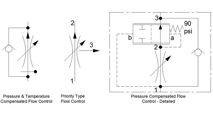
Flow Control Valves Non Pressure Compensated Valves Hydraulic Schematic Troubleshooting

China Fisher Gx Control Valve Dn 15 100 Manufacturers Suppliers And Company Discount Products Shaanxi Wantong Automation Equipment Co Ltd

Valve Positioners Basic Principles Of Control Valves And Actuators Automation Textbook
Control Valve Diagram のギャラリー
Chapter 10 Directional Control Valves Part 4 Hydraulics Pneumatics

Reverse Acting Diaphragm Actuator Of A Pneumatic Control Valve Download Scientific Diagram
How A Pneumatic Valve Positioner Works Learning Instrumentation And Control Engineering

Valve Positioners Basic Principles Of Control Valves And Actuators Automation Textbook
Hydraulics Flow Control Valve Hydraulic Tutor Stuffworking Com

Pin On Instrumentation

Control Valve Encyclopedia Article Citizendium

4 Way 3 Position Control Valve Working Construction Youtube
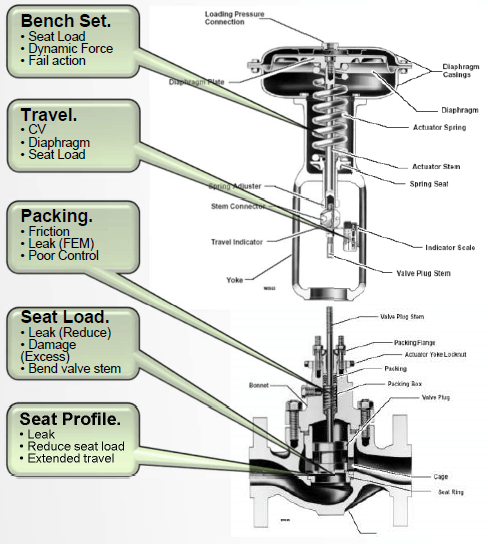
Control Valve Parts The Basics Kimray
Directional Control Valve

Nice Diagram Showing The Architecture Of A Control Valve Used In Boiler Hvac Chiller Plumbing And Other Applic Control Valves Miata Mx5 Control Engineering
Book 2 Chapter 18 Pressure Relief Valves Hydraulics Pneumatics

Reading Fluids Circuit Diagrams Hydraulic Pneumatic Symbols

Schematic Diagram Of Control Valve Test System Test System Figure 1 Download Scientific Diagram

Chapter 19 Control Of Actuators For Process Valves Engineering360

Accessories For Control Valves

Schematic Diagram Of 3 Way Control Valve For Precision Temperature Download Scientific Diagram
Piping And Instrumentation Symbols Instrumentation Tools
Control Valve Working Principle Control Valve Animation
Water Control Valves Flow Coefficient I C Sub V Sub I Diagram

Digital Control Valve Flow Control Valves
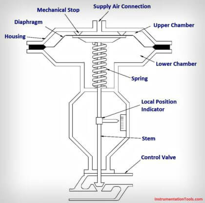
What Is A Pneumatic Actuator Instrumentationtools

How To Install A Control Valve And What Are The Types Of Actuators Used In Control Valves Instrumentation And Control Engineering

Pressure Control Valves Compound Pressure Relief Valve Hydraulic Schematic Troubleshooting
Multi Stage Height Control Valve Including Position Sensitive Pilot Signal And Pressure Boost For Vehicle Air Springs Diagram Schematic And Image 07

Schematic Diagram Of The Flow Control Valve Download Scientific Diagram
Q Tbn And9gcqikuy7d Lutfzjwmbwfz9emf S6sgclcdsc55uyxpfrrjpkxvu Usqp Cau

Pressure Valve Schematic Diagram Electrical Wiring Diagrams

How A Typical Control Valve Loop Works Learning Instrumentation And Control Engineering
Diagram Of Proportional Pressure Control Valve Calibration Download Scientific Diagram

Flow Control Valves Regulate Speed Hydraulics Pneumatics

Four Port Three Position Directional Control Valve Matlab
Valve Positioner Block Diagram Control Valves Instrumentation Forum

Digital Control Valve Principle Control Systems Engineering Control Valves Hydraulic Systems

Valve Positioners Basic Principles Of Control Valves And Actuators Automation Textbook
Directional Control Valves Open Center Sliding Spool Directional Control Valve Hydraulic Schematic Troubleshooting
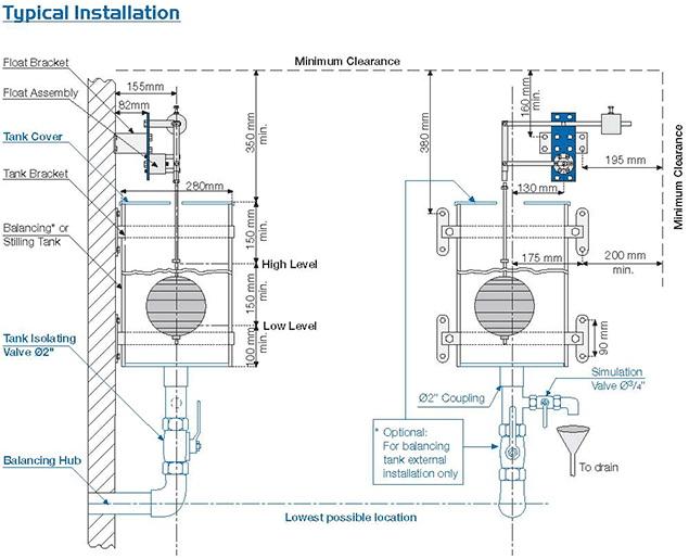
How To Install Tank Fill Control Valves Bermad

Schematic Diagram Of A Control Valve Download Scientific Diagram

Pneumatic Control Valve

Hydraulic Equipment Slowdown Nailing Internal Leakage

Code No P0628 Suction Control Valve Open

Pin On Instrumentation
Book 2 Chapter 8 Directional Control Valves Hydraulics Pneumatics

Directional Control Valves Explained
Q Tbn And9gcqfdw85qdb4rohdvjzcfcgsevxuizyc7vf U7ix54s Usqp Cau
Hydraulic Flow Control Valves Hydraulic Valve

Control Valve Diagram Articleshook
Relief Valve Wikipedia

How A Temperature Control Valve Works Learning Instrumentation And Control Engineering

Heater Control Valve Hcv Swartz Garage

Structure Of Pneumatic Control Valve Adapted From 8 Download Scientific Diagram
Hook Ups Detailed Engineering Of The Control Valve Assembly
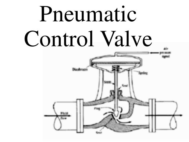
Pneumatic Control Valve
Basic Hydraulics Directional Control Valve Blog Teknisi
Bis Valves Products Rotary Control Valve 4r25

Flow Control Valves Pressure Compensated Valves Hydraulic Schematic Troubleshooting

Process Diagram Symbols Lowflow Valve Fractional Flow Control Valves Regulators
Reading Fluids Circuit Diagrams Hydraulic Pneumatic Symbols

Smart Control Valve Positioner Control Systems Engineering Control Valves Valve

Ven 11 Lift Axle Control Valve Lift Axle System
Understanding Pressure Control Valves Hydraulics Pneumatics

Proportional Solenoid Valve How They Work Tameson
Hydraulics Systems Diagrams And Formulas Cross Mfg
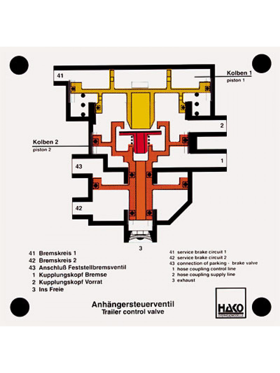
Trailer Control Valve Technolab Sa
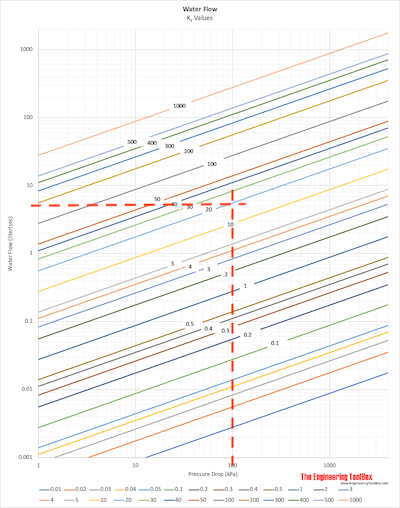
Water Control Valves Em K Sub V Sub Em Flow Coefficient Diagram
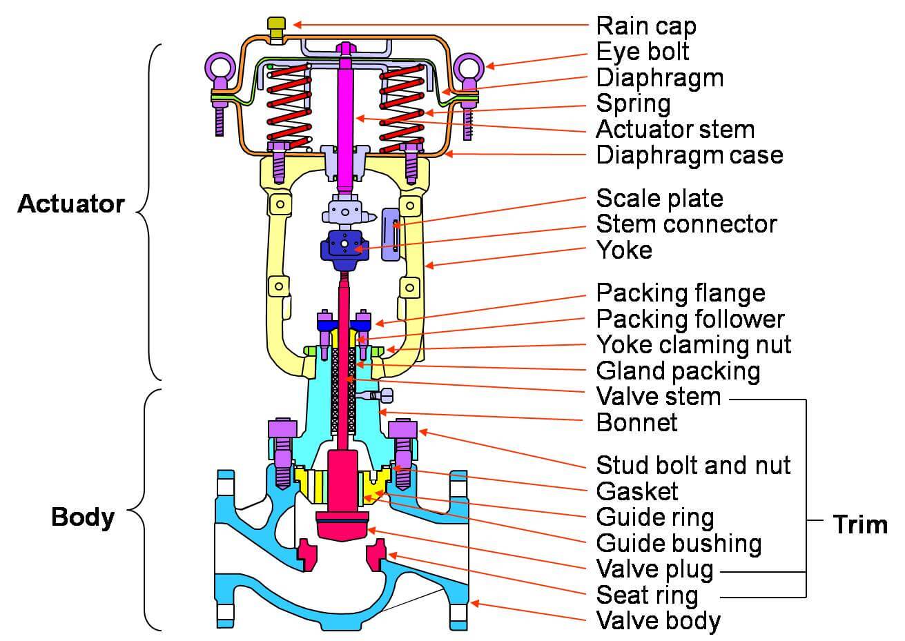
Basic Parts Of Control Valves Control Valve Functions
Globe Valve Ball Valve Gate Valve Flow Control Valve Png 681x507px Globe Valve Ball Valve Control
Hook Ups Detailed Engineering Of The Control Valve Assembly
Q Tbn And9gcq9h2gbrzqi9ptr49lihip8 Qzybektej4vytllkvgr9zv3yld9 Usqp Cau
Hydraulic Monoblock Solenoid Control Valve 1 Spool 13 Gpm 12v Dc

Control Valve Parts Name Basic Knowledge Of Control Valve Parts In Hindi Youtube
Hydraulic Symbology 3 Pressure Valves
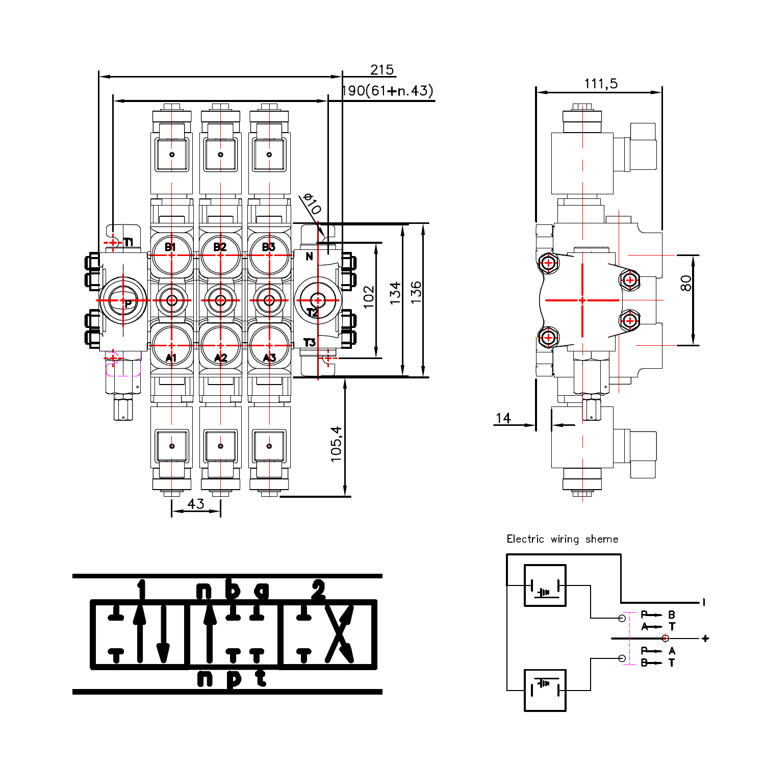
Hydraulic Solenoid Directional Control Valve Double Acting 2 Spool

Directional Control Valves Explained

3 Way Proportional Control Valve Download Scientific Diagram

Determining Control Valve Pressure Drop For Valve Sizing Neles
Directional Control Valves Solenoid Operated Directional Control Valves Hydraulic Schematic Troubleshooting

Fortis Jaya Signs And Symptoms Of A Bad Idle Air Control Valve When Engine Problems Occur In An Automobile Causing The Vehicle To Misfire Stall Backfire Or Not Start At All

Control Valve Instrumentation And Control Engineering
Heater Control Valve Diagram View Chicago Corvette Supply

Pressure Regulator Wikipedia

What Does A Flow Control Valve Do

Diagnostic Method For Detecting Control Valve Component Failure Diagram Schematic And Image 08
Valve Condition Monitoring Connected Services
Flow Control Valves Hydraulic Symbology 4

Lift Axle Control Valve Diagram Schematic And Image 02

Final Control Element An Overview Sciencedirect Topics

Chapter 12 Infinitely Variable Directional Valves Hydraulics Pneumatics
Control Valves And Their Principles Of Operation
Control Valve Sizing Basic Principles Of Control Valves And Actuators Automation Textbook
Hydraulic Symbology 3 Pressure Valves

Hydraulic Flow Control Valves Hydraulic Valve
Reading Fluids Circuit Diagrams Hydraulic Pneumatic Symbols

Control Valve Instrumentation And Control Engineering
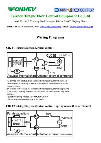
Tonhe Motorized Valve Wiring Diagrams Taizhou Tonhe Flow Control Equipment Co Ltd Pdf Catalogs Technical Documentation Brochure

Control Valve Sizing And Selection For Continuous Process Operations Processing Magazine

What Is A Directional Control Valve And What Are The Types Of Dcv Instrumentation And Control Engineering

Control Valve With Wide Flow Range
7 Trailer Control Valve Download Scientific Diagram
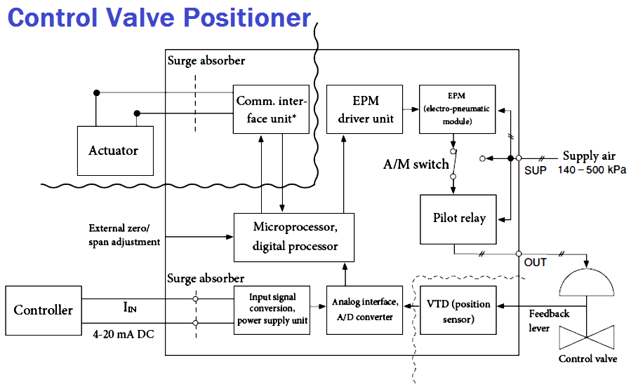
Control Valve Positioner Circuit Diagram Control Valves Instrumentation Forum


