Charging System Diagram
Example only Let's say the stator is rated for 10 amps x 13volt battery 10 x 13=130 watt charging system So you have a 130watt charging system in this example Now, you can take the wattage of all those electrical accessories and see if you're under or over your 130 watts and how much you have to play with Volt Meters You can check your.

Charging system diagram. Charging Page 2 of 3 • Honda Engine Charging System Charge wiring diagram honda gxv390k1det3 Coil Wires Charge Coil inspection chart in the appropriate shop manual Replace Just got a gx engine has the 10 amp charging system and coming from fly wheel were is the rectifier located on The wiring diagram is on page Honda gx, 18 amp. A car uses quite a lot of electricity to work the ignition and other electrical equipment If the power came from an ordinary battery, it would soon run downSo a car has a rechargeable battery and a charging system to keep it topped up The battery has pairs of lead plates immersed in a mixture of sulphuric acid and distilled water Half of the plates are connected to each terminal. Hearing a click or groan when starting electricstart engines;.
Start the engine One major difference in a generator and an alternator comes into play here Unlike an alternator, the generator will not charge well at an idle The voltage increases with the number of rpm The engine must be at 1,500 rpm to check the charging system. Onboard electronics aren’t operating properly;. If you haven't overhauled your VW's wiring system, it is likely the Volkswagen's wires are aged, dried out, brittle and cracked This is why we always recommend beginning your restoration project by overhauling your wiring We have created colored wiring diagrams for your convenience.
Description Wiring The 25 Hp Kohler pertaining to Kohler Engine Charging System Diagram, image size 778 X 6 px, and to view image details please click the image Here is a picture gallery about kohler engine charging system diagram complete with the description of the image, please find the image you need. If the charging system on your car has an external regulator, warm up the engine before performing the following test 1 Turn off the engine, lights, and all other accessories 2 Attach an engine tachometer according to the manufacturer's instructions 3. Battery won’t charge or is draining too quickly;.
I have a few basic electrical system diagrams that are helpful in understanding how the wiring system works They are not specific to any particular tractor and do not include safety switches All use the 5 post ignition switches for Magneto and for Battery Ignition I failed to i. Ok, recent thread on here drove me past the point of looking at wiring diagrams and giving direction Somethings are just easier explained with pictures and tested against a known good working system So in an effort to help others, I tore my own truck apart in the dark outside in Alaskan. Prev 446b backhoe loader electrical system schematic Next 416C, 426C, 428C, 436C AND 438C BACKHOE LOADER WITH EUROPEAN CAB ELECT SYSTEM Press CTRL SCROLL to zoom in/out.
Charging System Wiring Diagram For Pt Cruiser Manual EBooks – Briggs And Stratton Charging System Wiring Diagram Wiring diagram also offers beneficial suggestions for tasks that may require some extra equipment This guide even consists of ideas for extra provides that you could need to be able to complete your tasks. Charging System/Battery Replacement Remove the front cover ((43) Disconnect the regulator / rectifier wire coupler Remove the 2 regulator / rectifier setting bolts attached to the headlight stay Install in the reverse order of removal AC Generator Inspection NOTE Disconnect the 4P coupler of the generator cord. Diagrams and Schematics Index Section A Front/Rear Axle Assemblies and Suspension Wheels Section B Brake Assemblies and Components Hydraulic Brake System Master Cylinder Brake Booster Clutch/Brake Pedals Section C Steering Components Steering Column Steering Box Steering Linkage Section D Frame and Body.
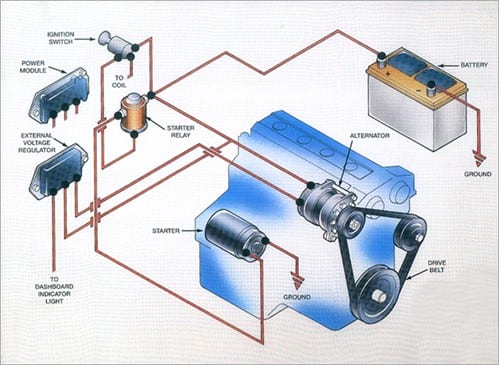
If you use a key to start your lawn mower, snow blower or outdoor power equipment, the small engine includes an electrical charging system with a battery and alternator. Proper battery management, including switching and charging, is essential for safe and reliable operation The following basic wiring diagrams show how batteries, battery switches, and Automatic Charging Relays are wired together from a simple single battery / single engine configuration to a two engine, one generator, and four battery bank system. Ford alternator wiring diagram internal regulator Among all the Ford alternator wiring diagrams above, this is the most complicated one It consists of ignition switch, fuse panel, engine compartment relay box, instrument cluster and many more It requires advanced knowledge to fix an alternator with this diagram.
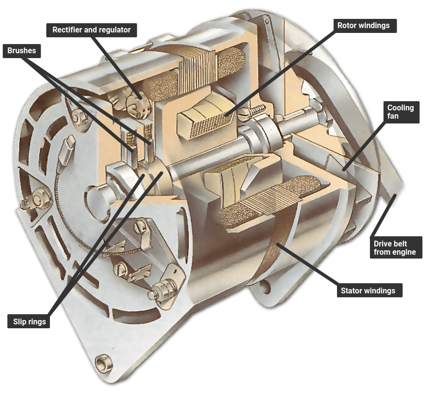
The charging system requires little maintenance The battery should be fully charged and connections kept clean and tight Diagnosis of charging system problems is typically straightforward Problems may be electrical or mechanical The troubleshooting flow diagram on the next page lists the most common charging system problems, the possible. 7 Charging Wires The function of charging wires are to connect every component of the charging system, there are at least two types of wires standard wire and B wire The standard wire has a small diameter like the car’s electrical wiring in general, the function of this wire is connecting each terminal on the entire charging system. Parts of charging system Charging system is a series of electronics that are made to suply electricity for the vehicle We know that batery use as source of electricity, but battery is only save the electricity and can not produce it So, it should be a system that use to produce electricity to charge the battery and suply all electrical load on vehicle.
Schematic Circuit Diagrams, rather than wiring harness diagrams are usually preferred for troubleshooting, because of their ability to show current and potential system functions A schematic diagram is made up of consistent geometric symbols for the components, and their controls and connections. This is a half wave type charging system and when the engine is not running and the key switch is in the off position, the system is isolated from the battery to prevent back feed When the engine is running, the charging system needs to have a a complete circuit back to the battery, and if not then components like the regulator/rectifier will. The charging system requires little maintenance The battery should be fully charged and connections kept clean and tight Diagnosis of charging system problems is typically straightforward Problems may be electrical or mechanical The troubleshooting flow diagram on the next page lists the most common charging system problems, the possible.
Charging system problems requires a thorough understanding of the system components and their operation Operation When the engine is running, battery power energizes the charging system and engine power drives it The charging system then generates electricity for the vehicle's electrical systems At low speeds with some electrical loads "on. Description Wiring The 25 Hp Kohler pertaining to Kohler Engine Charging System Diagram, image size 778 X 6 px, and to view image details please click the image Here is a picture gallery about kohler engine charging system diagram complete with the description of the image, please find the image you need. If the charging system on your car has an external regulator, warm up the engine before performing the following test 1 Turn off the engine, lights, and all other accessories 2 Attach an engine tachometer according to the manufacturer's instructions 3.
Routine Charging System Repairs & Maintenance Turning the key in your ignition, and only getting a click, a choking sound, or silence is a horrible feeling Your vehicle’s startup needs to be automatic and reliable every time you get behind the wheel That’s what our team promises with our routine charging system maintenance services. THE BATTERY CHARGING WIRE (Please refer to “The ORIGINAL CHEVY SYSTEM” diagram) In the case of voltage drop at the long “battery charging wire,” the small amount of voltage drop was actually a good thing. Charging System & Wiring DiagramAmazon Printed Bookshttps//wwwcreatespacecom/Amazon Kindle Editionhttp//wwwamazoncom/AutomotiveElectronicDiagn.
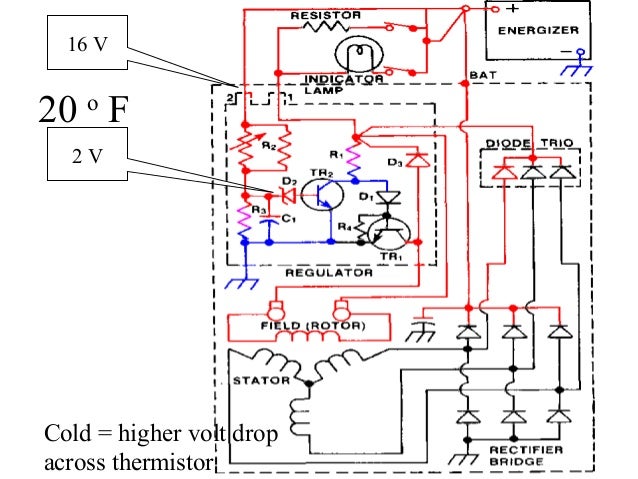
Charging System Operation 151 Figure 87 A single diode in the circuit results in halfwave rectification (Delphi Automotive Systems) voltage reverses at the start of the next rotor revolution, the current is again allowed through the diode from X to Y An AC generator with only one conductor and. The following tests are performed when the charging system is operating normally but the battery discharges, either while the engine is running or while the engine is off aTurn OFF the ignition switch, and connect a DMM (set to measure DC amps) as shown Use a shunt if the system you are testing. Ford alternator wiring diagram internal regulator Among all the Ford alternator wiring diagrams above, this is the most complicated one It consists of ignition switch, fuse panel, engine compartment relay box, instrument cluster and many more It requires advanced knowledge to fix an alternator with this diagram.
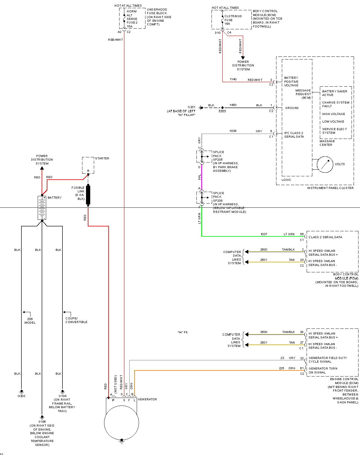
You might want to check your car's starting and charging system to identify any issues We've got everything you need to know to ta. Please check the two attached diagrams that show a different wire for the charging light The "Starting and Charging" diagram shows a GreenRed, the "Instrument Panel" diagram shows a YellowBlack wire. Such is the case with the charging system Our C Apache still uses a 12volt/35amp generator that was common from Chevy cars and trucks For Chevrolet vehicles with air conditioning, a 35amp generator was used, but trucks were work vehicles and often void of any creature comforts.
Alternator Wiring Diagram Mustangs Back to the Tech Articles * Please be advised that this information is for suggestion only and is based on prior experience We at CJ Pony Parts can not be held responsible or liable for any mistakes or injuries connected with the topics covered Stay Connected Events;. Charging System/Battery Replacement Remove the front cover ((43) Disconnect the regulator / rectifier wire coupler Remove the 2 regulator / rectifier setting bolts attached to the headlight stay Install in the reverse order of removal AC Generator Inspection NOTE Disconnect the 4P coupler of the generator cord. Charging System Battery & Alternator Test How to test a small engine charging system, battery & alternator?.
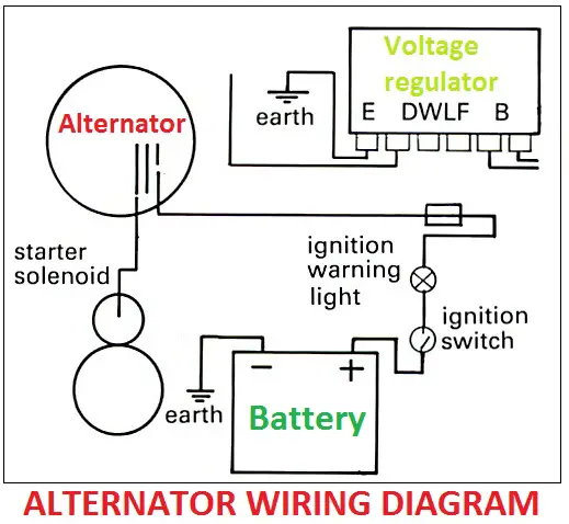
A typical campervan split charging system has a device that connects the battery used to start the engine to the leisure battery when the engine is running Once the engine is running, the power from the alternator can now flow to both your starter battery and leisure battery, charging both batteries simultaneously. The flywheel for charging system motors has more & stronger magnets Many manufacturers these days have decided not to produce two different flywheels When you add the charging coil to the engine, the magnets are already there & are capable of exciting the coil beyond it’s maximum output rating Now, you CAN overamp your charging coil for a. Mopar Charging Systems up to 1969 Diagram #1 shows the basics of the early alternator / voltage regulator (VR) design There are 2 brushes in the alternator, each one has a field terminal, one is labeled "FLD", the other is labeled "GND".
A wiring diagram is a type of schematic which uses abstract pictorial icons to reveal all the interconnections of components in a system Electrical wiring representations are made up of two things signs that represent the components in the circuit, as well as lines that stand for the links between them. Charging System Operation 151 Figure 87 A single diode in the circuit results in halfwave rectification (Delphi Automotive Systems) voltage reverses at the start of the next rotor revolution, the current is again allowed through the diode from X to Y An AC generator with only one conductor and. MOPAR CHARGING SYSTEM PRE1970 Diagram #1 shows the basics of the early alternator / voltage regulator design There are 2 brushes in the alternator, each one has a field terminal, one is labeled "FLD", the other is labeled "GND" The GND brush is grounded with the brush mounting screw The other brush is the () brush (or field) and attached.
Charging System Alternator Schematic Diagrams Manuals;. 1) If the charging light is wired wrong can that prevent the system from charging?. Charging System 12 Volt Alternator Wiring Diagram from ipinimgcom Effectively read a cabling diagram, one offers to know how the components inside the method operate For example , in case a module will be powered up and it sends out a signal of 50 percent the voltage in addition to the technician would not know this, he would think he.
7 Charging Wires The function of charging wires are to connect every component of the charging system, there are at least two types of wires standard wire and B wire The standard wire has a small diameter like the car’s electrical wiring in general, the function of this wire is connecting each terminal on the entire charging system. The Thunderbolt is a typical charging regulator the has an overcharging protection at 14 volts and a discharge protection of 105 volts so it does have some features that make it “smarter” than a standard on/off charging system. If the charging system on your car has an external regulator, warm up the engine before performing the following test 1 Turn off the engine, lights, and all other accessories 2 Attach an engine tachometer according to the manufacturer's instructions 3.
Description Wiring The 25 Hp Kohler pertaining to Kohler Engine Charging System Diagram, image size 778 X 6 px, and to view image details please click the image Here is a picture gallery about kohler engine charging system diagram complete with the description of the image, please find the image you need. Hyundai Santa Fe Alternator Schematic Diagrams Hyundai Santa Fe DM 1318 Service Manual / Engine Electrical System / Charging System / Alternator Schematic Diagrams Circuit Diagram Alternator Components and Components Location. Hot Rod Wiring Diagram Please Note This diagram was designed for 12 volt systems, but can also be used for 6 volt systems If used for 6 volt, make all the wires heavier by 2 gauges For example 14 gauge wire will become 12 gauge, 10 gauge will be 8 gauge, etc.
Charging System & Wiring DiagramAmazon Printed Bookshttps//wwwcreatespacecom/Amazon Kindle Editionhttp//wwwamazoncom/AutomotiveElectronicDiagn. Charging System Test Steps *** All steps must be done with a fully charged battery The engine must be running and an electrical load applied to the system (lights , etc) An Analog Voltmeter is recommended but a Digital Voltmeter will work *** Step 4 Key ON/Engine OFF Unplug alternator. Note If you use a key to start your lawn mower, snow blower or outdoor power equipment, the small engine includes an electrical charging system with a battery and alternator.
For charging it the chargingsystem should provide a voltage of about 144 Vdc and this should be a constant voltage at all enginespeeds The generator itself is located in or on the engine, and on most bikes there is a separate regulatorrectifier unit located somewhere on the frame. Charging System Wiring Diagram Geo Ignition Switch Tomosa35 Jeep Wrangler Waystar Fr The Mazda 95probe Charging System Circuit Automotive Diagram Seekic Com The Alternator Ford Crown Victoria Alternator Wiring Diagrams Advanced Auto Electrical Systems Troubleshooting. Such is the case with the charging system Our C Apache still uses a 12volt/35amp generator that was common from Chevy cars and trucks For Chevrolet vehicles with air conditioning, a 35amp generator was used, but trucks were work vehicles and often void of any creature comforts.
Charging System Wiring Diagram For Pt Cruiser Manual EBooks – Briggs And Stratton Charging System Wiring Diagram Wiring diagram also offers beneficial suggestions for tasks that may require some extra equipment This guide even consists of ideas for extra provides that you could need to be able to complete your tasks. A wiring diagram is a type of schematic which uses abstract pictorial icons to reveal all the interconnections of components in a system Electrical wiring representations are made up of two things signs that represent the components in the circuit, as well as lines that stand for the links between them. 7 Charging Wires The function of charging wires are to connect every component of the charging system, there are at least two types of wires standard wire and B wire The standard wire has a small diameter like the car’s electrical wiring in general, the function of this wire is connecting each terminal on the entire charging system.
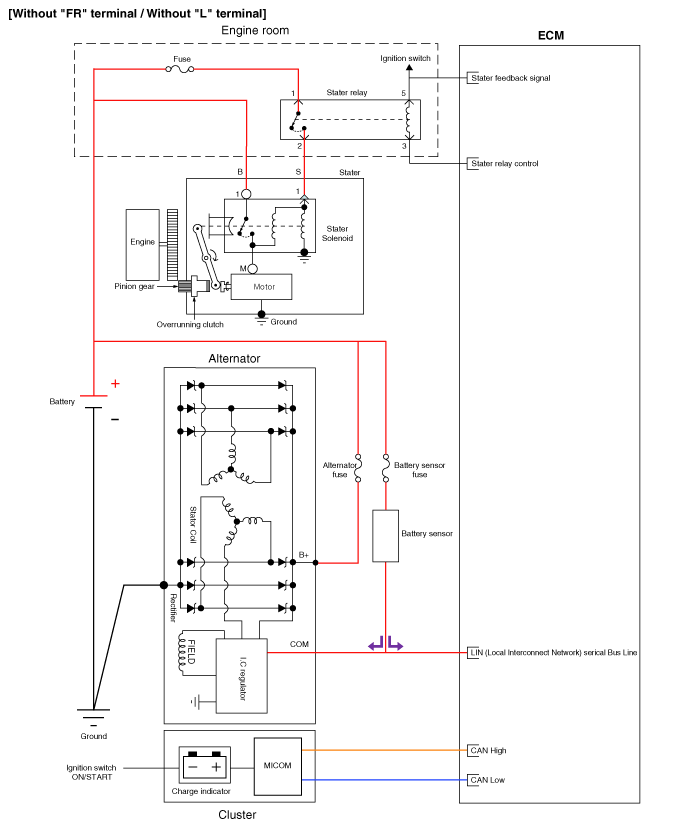
Hyundai Tucson Alternator Schematic Diagrams Charging System
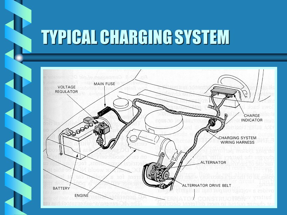
Automotive Charging Systems Chapter 7 Purpose Of Charging System B Convert Mechanical Energy Into Electrical Energy B Recharge Battery B Provide Power Ppt Download

Charging System Definition Functions Parts Working Studentlesson
Charging System Diagram のギャラリー

Schematic Diagram Of Ev And Charging System Download Scientific Diagram
Http Www Autoshop101 Com Forms Elec05 Pdf

Escape City Com View Topic 03 Charging System Diagram
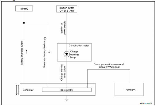
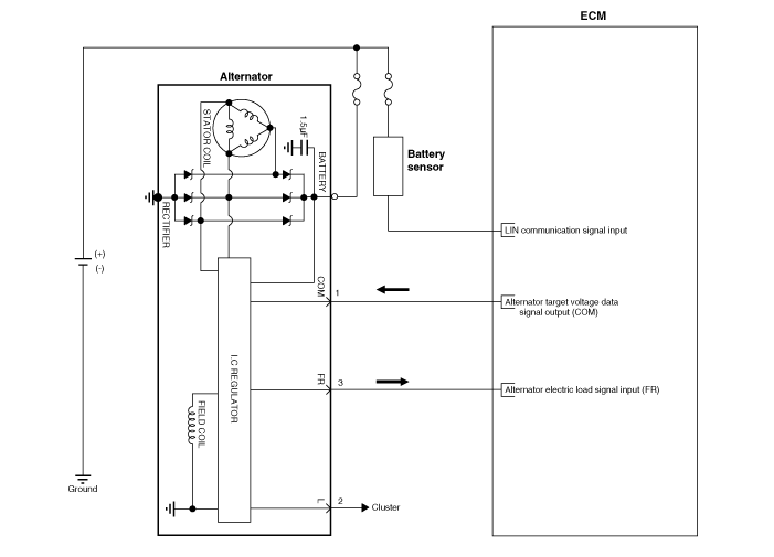
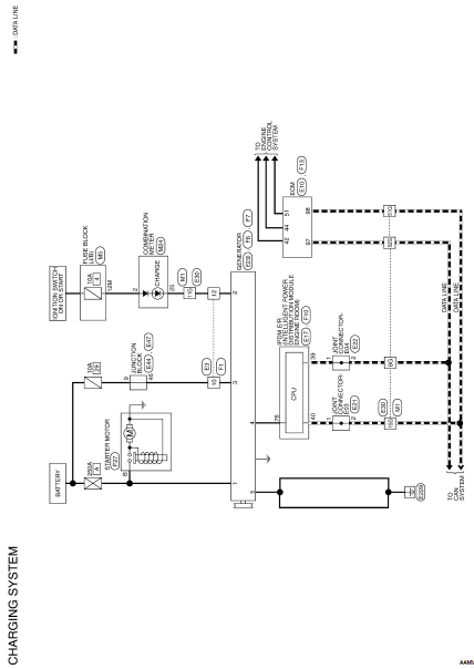
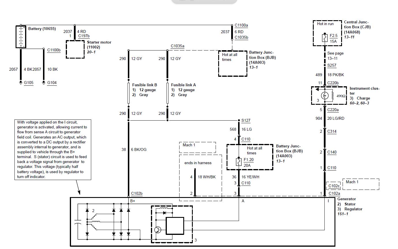
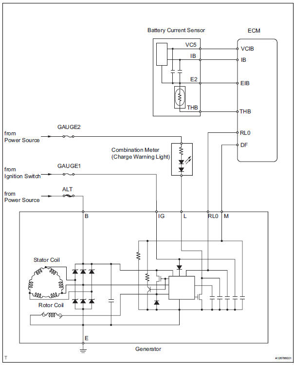
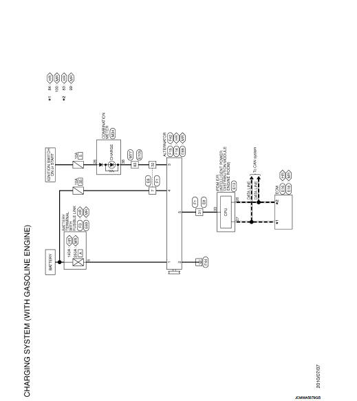
Nissan Sentra Service Manual Charging System System Description Charging System Electrical Power Control

Diagram Ford Focus Charging System Diagram Full Version Hd Quality System Diagram Endiagrampq Aricadore It

Training Manual

Automotive Charging Systems A Short Course On How They Work Carparts Com Car Alternator Alternator Electrical Circuit Diagram

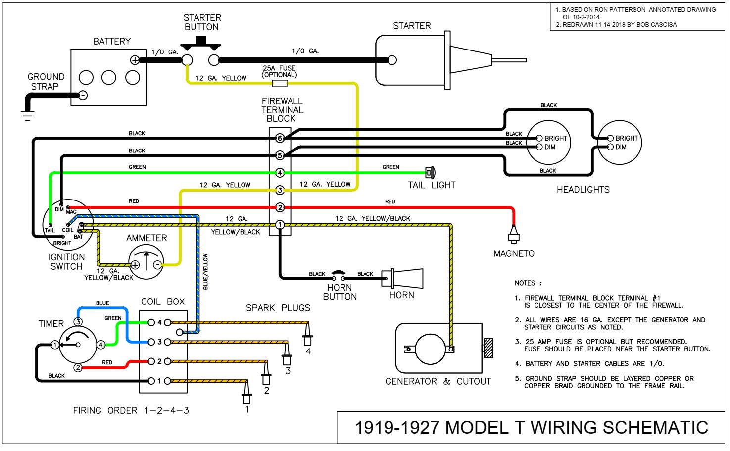
Ignition And Charging System Diagram Vw Dune Buggy Dune Buggy Auto Repair

Charging System Definition Functions Parts Working Studentlesson
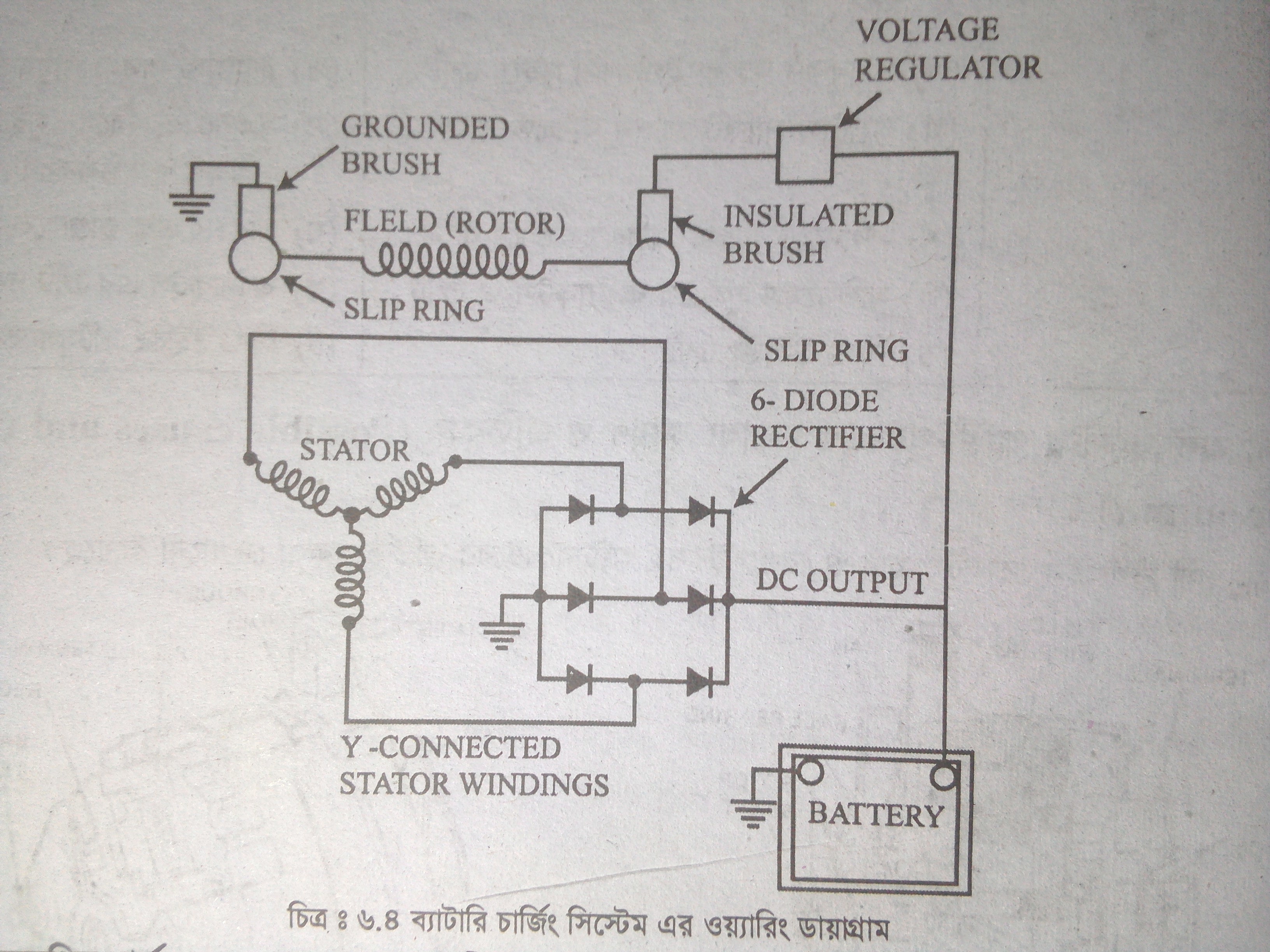
Simple Wearing Diagram Of Battery Charging System Steemit
Nissan Altima 07 12 Service Manual Charging System Component Diagnosis Charging System
6 Volt Charging System Wiring Diagram 13 Ford Fusion Speaker Wiring For Wiring Diagram Schematics

Circuit Diagram Of A Fundamental Battery Charging System With Input Download Scientific Diagram
How To Install A Charging System On Your Motorcycle Youtube
Q Tbn And9gctqcr2ctlbhmuxjmmyh79o 3nug819nmct7497szk2evr7cphlh Usqp Cau

Overall Structure Schematic Diagram Of The Robot Wireless Charging System Download Scientific Diagram

Power Equipment Engine Charging Systems And Dc Circuits

Automotive Charging Systems Ppt Download
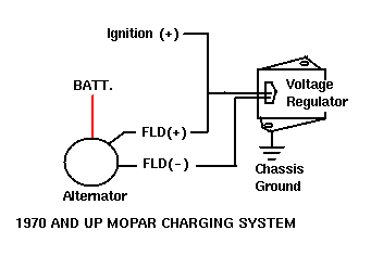
Mopar Charging Systems
Hafeisaima Car Charging System Circuit Diagram Battery Charger Power Supply Circuit Circuit Diagram Seekic Com

Engine Starting And Charging System Youtube
Circuit Diagram Of A Fundamental Battery Charging System With Input Download Scientific Diagram
Kia Sportage Schematic Diagrams Charging System

New Wiring Diagram Car Charging System Diagram Diagramtemplate Diagramsample Mitsubishi L0 Ford Mustang Mustang

Technical Article How A Motorcycle Charging System Works Electrospo Electrosport
Update Car Charging System Car Construction
Gm Alternator Wiring Ricks Free Auto Repair Advice Ricks Free Auto Repair Advice Automotive Repair Tips And How To

Ignition And Charging System Diagram Vw Dune Buggy Dune Buggy Auto Repair
03 04 Mustang Cobra Charging System

Motorcycle Charging System Wiring Diagram 12v Wiring Schematic Diagram
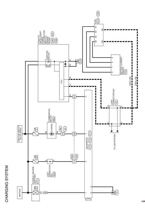
Nissan Sentra Service Manual Wiring Diagram Charging System Electrical Power Control

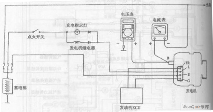
1994 Mazda Rx 7 S At Starting System And Charging System Wiring Diagram My Blog
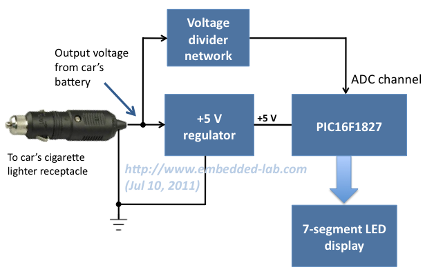
Voltage Monitor For Car S Battery And Its Charging System Embedded Lab

Wiring Diagrams Toyota Sequoia 01 Repair Toyota Service Blog

04 F150 Charging System Wiring Diagram Wiring Diagram Solid Global A Solid Global A Navicharters It
Q Tbn And9gctgxjs59lk Uyqief3x2morgsnpznprvt19 M Pp5f33pswn H Usqp Cau
Charging System Automobile

Charging System Tests

Block Diagram Of The Proposed Charging System Download Scientific Diagram

Charging System Block Diagram Download Scientific Diagram
Subaru Legacy Service Manual Charging System Wiring Diagram Wiring System

Block Diagram Of Battery Solar Charging System Download Scientific Diagram
Http Www Autoshop101 Com Forms Elec05 Pdf

Diagram 1996 F250 Charging Wiring Diagram Full Version Hd Quality Wiring Diagram Diagramloewem Chihuahuaboutique It

New Wiring Diagram Car Charging System Diagram Diagramtemplate Diagramsample Electrical Circuit Diagram Car Alternator Alternator
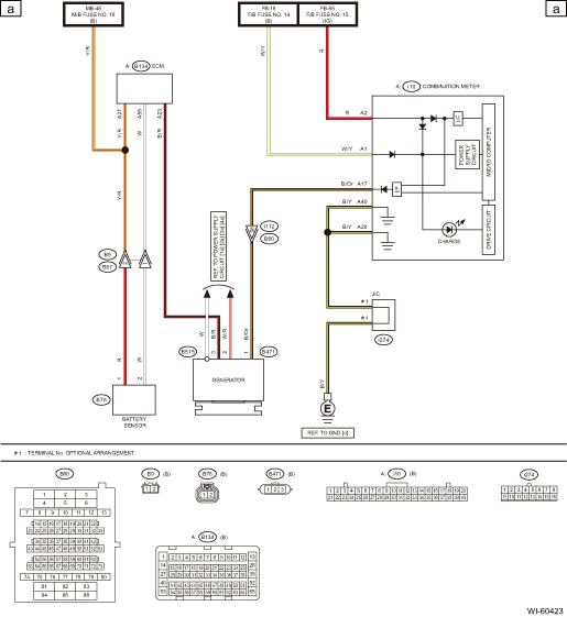
Hyundai Santa Fe Alternator Schematic Diagrams Charging System Engine Electrical System

Ls1 Charging System Third Generation F Body Message Boards
Troubleshooting Alternator And Charging System Problems Axleaddict A Community Of Car Lovers Enthusiasts And Mechanics Sharing Our Auto Advice
Starting Charging Top Tread Tyres

Charging System Wiring Diagram Geo Ignition Switch Wiring Diagram Tomosa35 Jeep Wrangler Waystar Fr

Wiring Diagrams Automotive Charging System Opel Corsa Utility Wiring Diagram Stereoa Yenpancane Jeanjaures37 Fr

The Main Circuit Schematic Diagram Of Charging System For Energy Download Scientific Diagram
Starting Charging System Infographic Diagram All Stock Vector Royalty Free
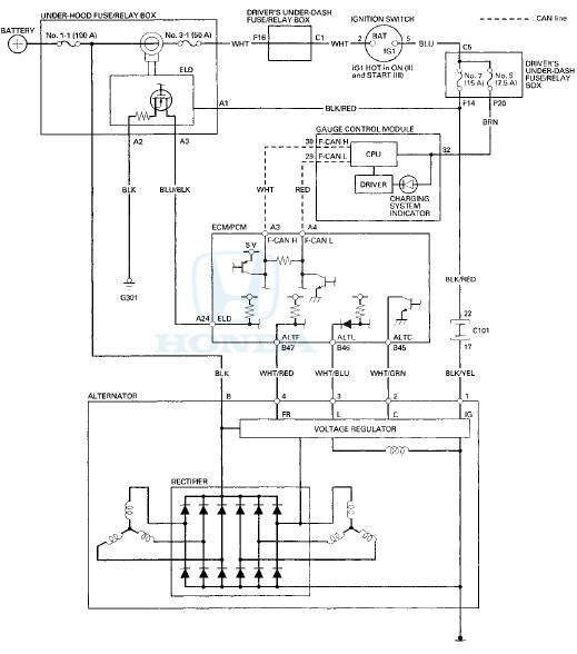
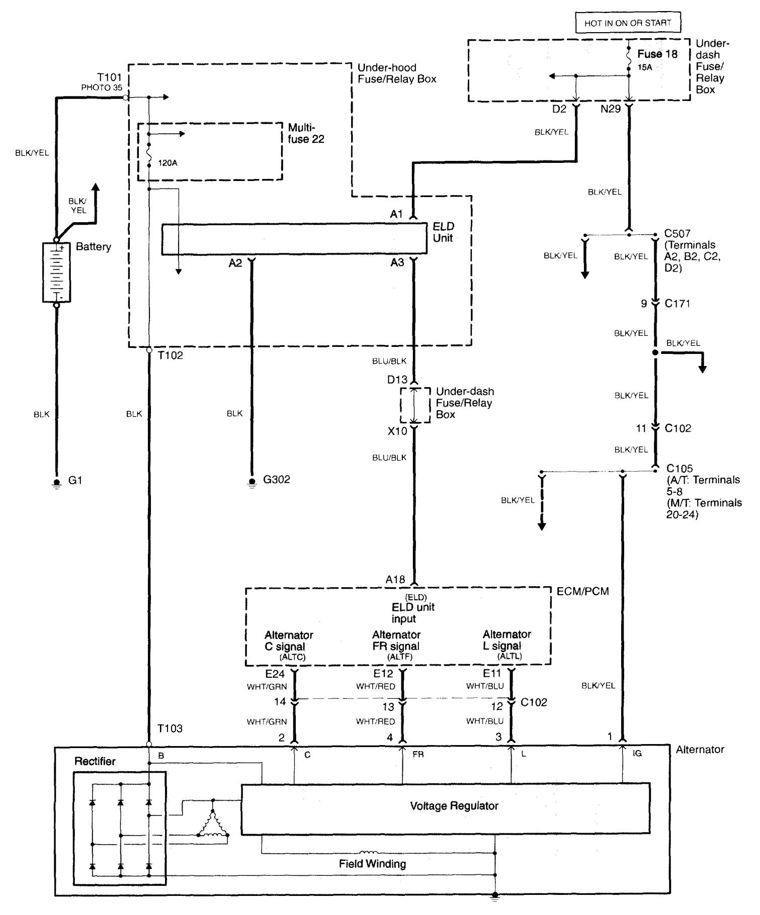
Acura Integra 1991 1992 Wiring Diagrams Charging System Carknowledge Info
Mz Alternator Charging System Diagram
Charging System Wiring For A Bodies Only Mopar Forum
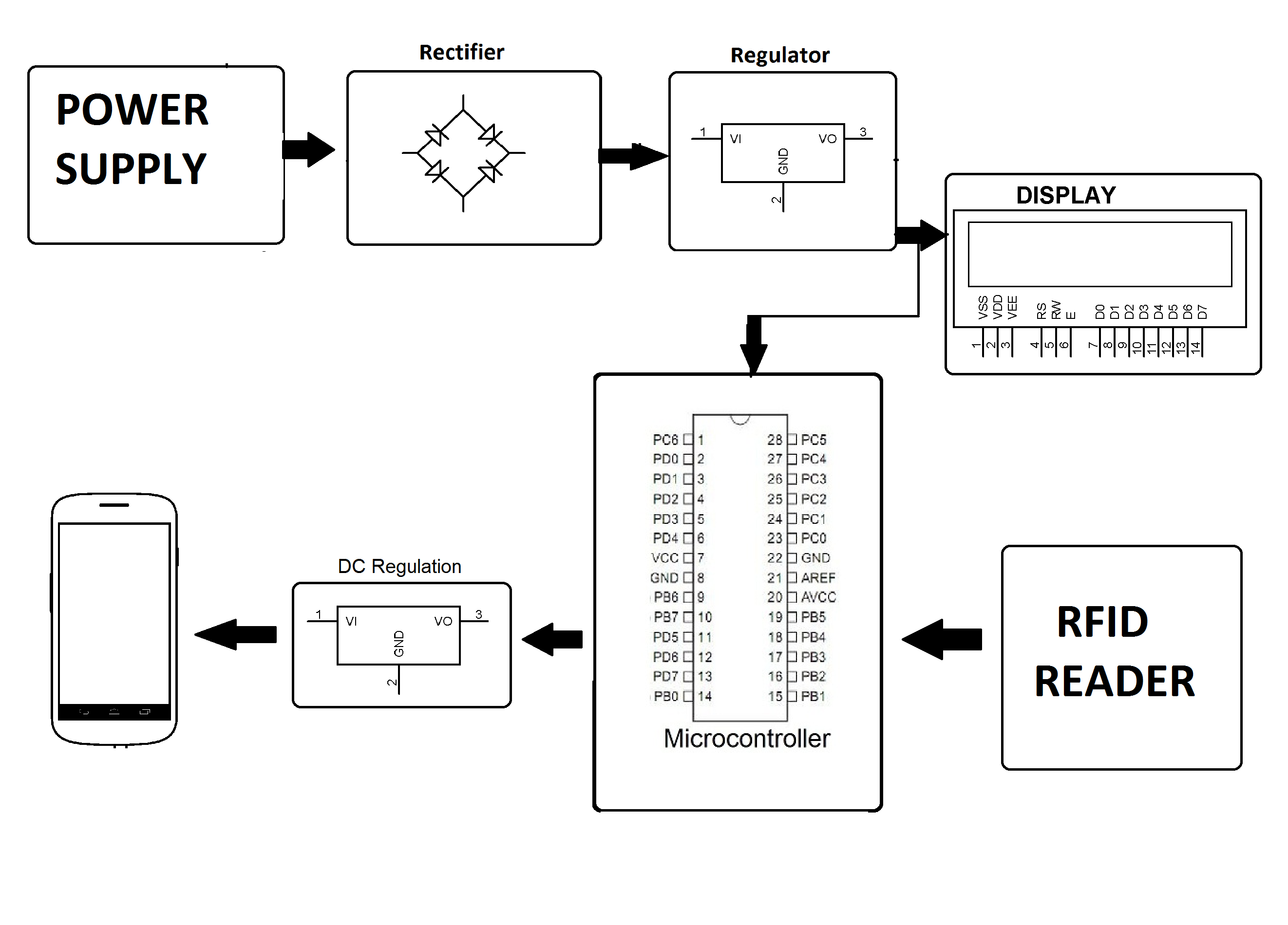
Rfid Mobile Charging System
Toyota Tacoma 15 18 Service Manual System Diagram Charging System 2gr Fks Charging
3
Principles Of Operation Of Charging System Automobile

Diagram Wiring Diagram For Car Charging System Full Version Hd Quality Charging System 1tonguediagram Museodiocesanobrescia It

Charging System Wiring Diagram Youtube
Alternator Not Charging Honda Tech Honda Forum Discussion

How Does The Car Charging System Work Youtube
Principle Diagram Of The Wireless Charging System Of Electric Vehicles Download Scientific Diagram
Q Tbn And9gcrx Nmuhpjbyltpbhydqauwibk4cy1hsvlmybydkdxszr1oysuu Usqp Cau
Toyota 4runner Charging System 1gr Fe Battery Charging Service Manual

New Wiring Diagram Car Charging System Diagram Diagramtemplate Diagramsample Alternator Electrical Circuit Diagram Electrical Diagram
04 F150 Charging System Wiring Diagram Wiring Diagram Solid Global A Solid Global A Navicharters It

Wiring Diagrams Toyota Sequoia 01 Repair Toyota Service Blog

Charging System Tests
Honda Accord Circuit Diagram Charging System Engine Electrical Honda Accord Mk8 08 12 Service Manual
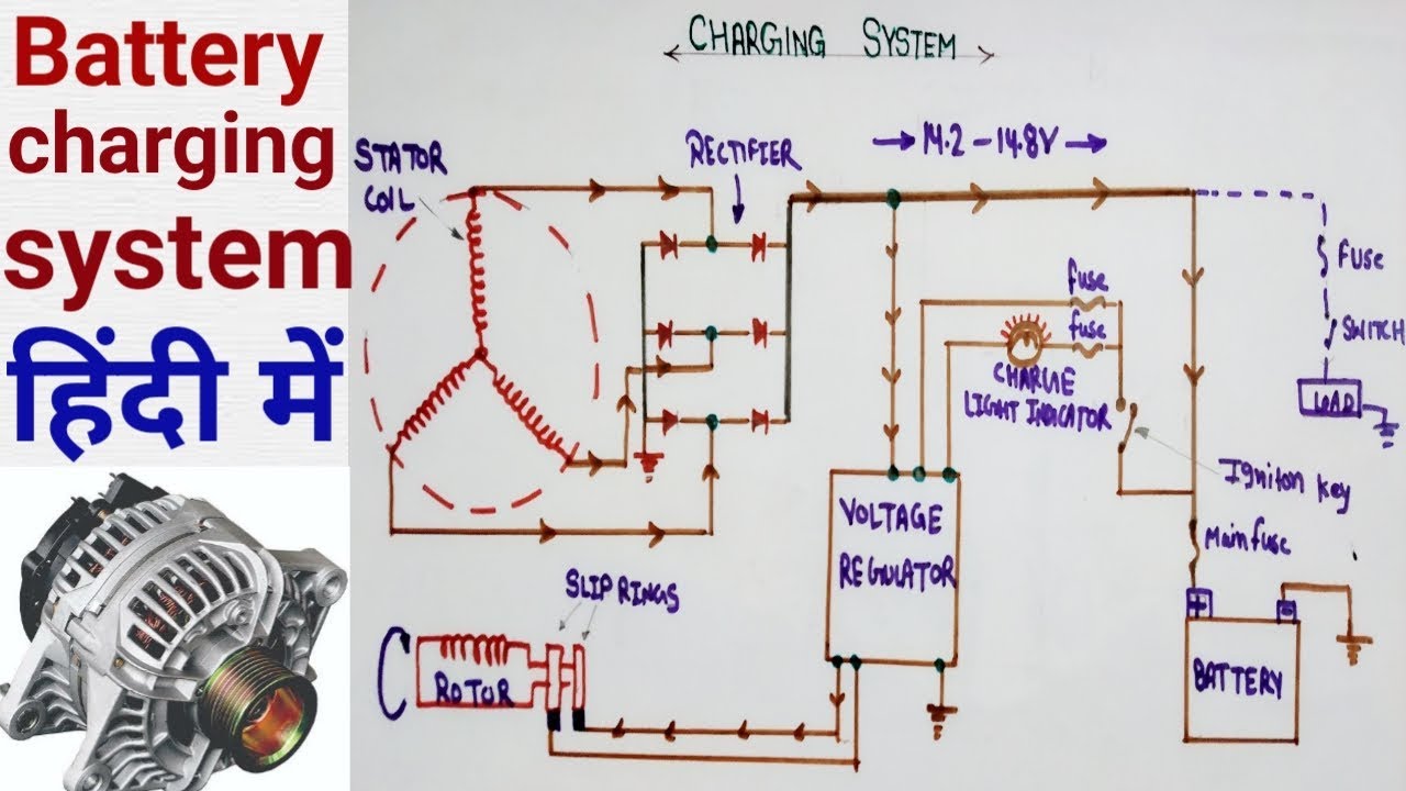
Alternator Circuit Diagram Battery Charging System Components Of Alternator In Hindi Youtube

A Logical Diagnostic Process Improves Charging System Diagnosis Clore Info
Acura Tl 06 Wiring Diagrams Charging System Carknowledge Info

14 100 Type B 3 Phase Field Excited Reg Rec Wire Diagram Revival Cycles

29 Briggs And Stratton Charging System Diagram Wiring Diagram List Briggs Stratton Stratton Briggs

Charging Systems

Prestolite Leece Neville
Toyota Rav4 Service Manual Precaution Charging System 2az Fe Charging
Http Www Autoshop101 Com Forms Elec05 Pdf

Air Main Charging System Diagram Kaeser Know How
How The Charging System Works How A Car Works

Block Diagram Representing The Vehicle Charging System Download Scientific Diagram

Motorcycle Charging System Wiring Diagram 12v 1990 Suburban Door Lock Actuator Wiring Diagram Hondaa Accordd Ati Loro Jeanjaures37 Fr

Block Diagram Of The Proposed Wireless Battery Charging System For A Download Scientific Diagram
Service Charging System Corvetteforum Chevrolet Corvette Forum Discussion
Ford Charging Wiring Diagrams Wiring Diagrams Join Region Tele B Region Tele B Tinchite It
Charging System Sun Auto Service
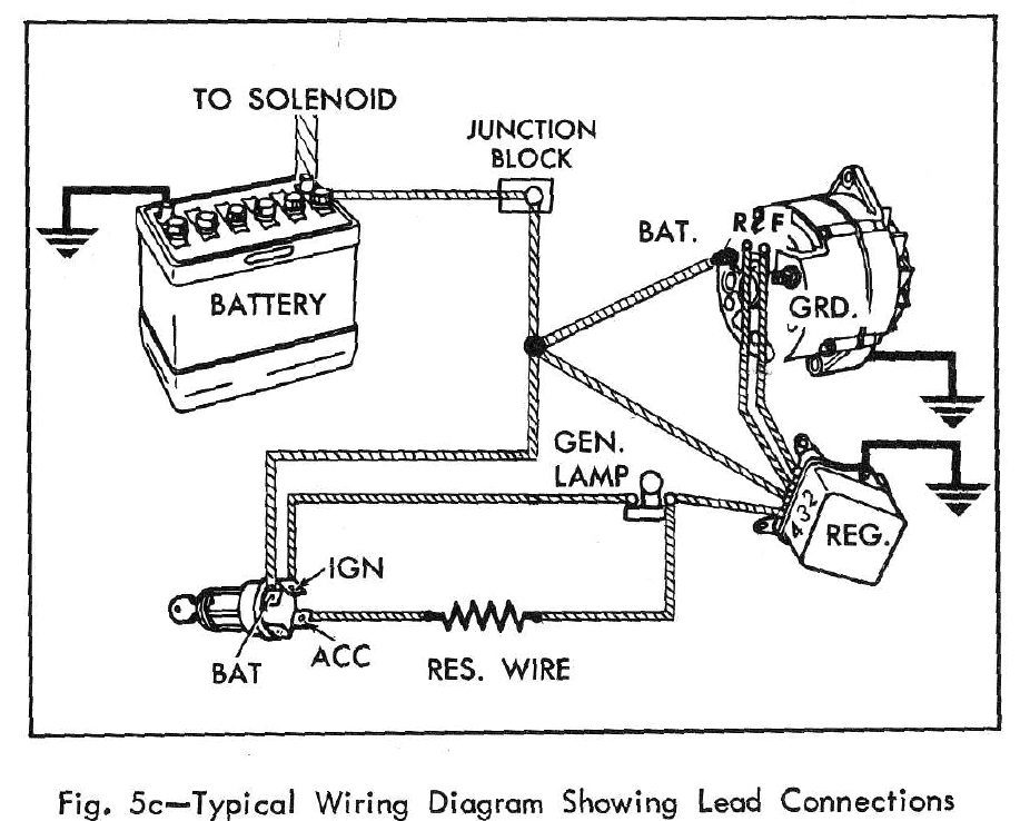
Diagram 19 Camaro Wiring Diagram Charging System Full Version Hd Quality Charging System Aurorawiring1h Dancingnevada It

Car And Deep Cycle Battery Frequently Asked Questions Faq Section 5
Charging System Wiring Diagram Youtube

Chevy Charging Wiring Diagram Wiring Diagram Cycle Dana B Cycle Dana B Bookyourstudy Fr

New Wiring Diagram Car Charging System Diagram Diagramtemplate Diagramsample
Wiring Diagram Charging System Nissan Juke Service And Repair Manual

Harley Davidson Charging System Wiring Diagram 800 Ford Tractor 12 Volt Wiring Diagram Code 03 Honda Accordd Waystar Fr

The Schematic Diagram Of Charging System For The Energy Storage Type Download Scientific Diagram

Wiring Diagrams Automotive Charging System Silverado Trailer Wiring Harness Wire Diag Yenpancane Jeanjaures37 Fr

Block Diagram Of Ev Charging System Download Scientific Diagram

Charging System Definition Functions Parts Working Studentlesson

Briggs And Stratton Charging System Diagram Briggs Stratton Briggs Stratton


