Charging System Car Alternator Wiring Diagram
A charging system voltage drop check can help you locate the source of an undercharge or overcharge condition due to problems in the wiring or connections between the battery and alternator 1 Start the engine and let it idle.

Charging system car alternator wiring diagram. Figure 1 DA Plug connects to the coil terminal through the ballast resistor if there is one Charge wire connects from the alternator to the battery through the the resistor or directly to the key switch itself (switched side) This wiring configuration will excite the alternator to start charging when the engine is running at low RPM’s. Charging System 12 Volt Alternator Wiring Diagram from ipinimgcom Effectively read a cabling diagram, one offers to know how the components inside the method operate For example , in case a module will be powered up and it sends out a signal of 50 percent the voltage in addition to the technician would not know this, he would think he. The Wiring & Cabling Wiringthis is without doubt where many people get it wrong and end up with a system that may work, BUT barely, and nowhere near as well as it could and should, doing it right can double the usable capacity of your auxiliary batteries over and above what many people normally have, and it will also help them charge much faster, and in turn they will last longer too.
Difference in wiring compared to standard alternators. Some other tidbits available from AC Delco for wiring up a 10SI, is wiring package (for those 6 to 12volt conversions) This contains the terminal connector AND an extra resistance wire pigtail to connect to the ignition system (don't use a ballast resistor if you use a resistance wire) Also available is an ammeter package (). Volvo 240 Alternator Wiring Diagram – There are many howto videos you could choose for auto repairs From a straightforward wheel alteration to changing your fuel filter are available in online video form These video clips can take you thru every single part of creating the maintenance and could help you save some time and the cost of consuming it to a mechanic.
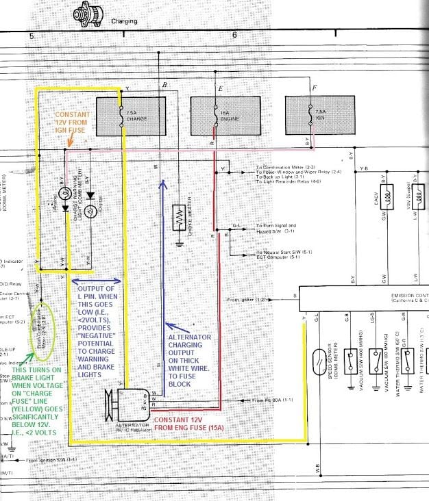
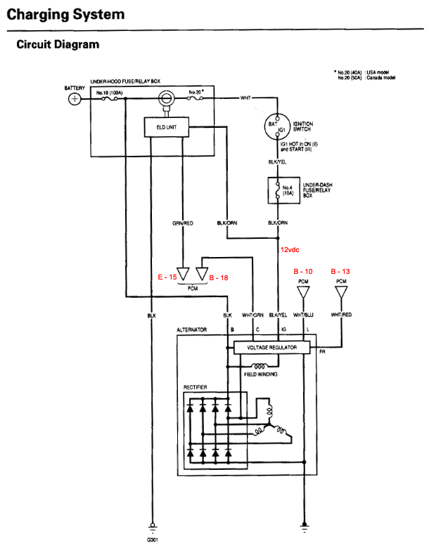
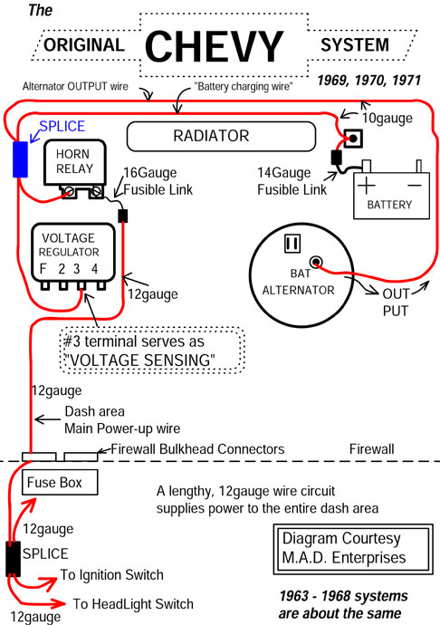
It wants to know if the charging voltage is reaching the fuse box. New Wiring Diagram Car Charging SystemAllowed in order to our blog site, in this particular time period I’ll teach you regarding wiring diagram car charging systemAnd today, here is the initial impression alternator charging system wiring diagrams body of knowledge from wiring diagram car charging system, sourcecrownvicnet. So if your car has a dynamo, and its output is inadequate, it makes sense to swap a dynamo for an alternator Removing the old dynamo and fitting the alternator are fairly straightforward The main difficulty is mounting the alternator, because it is a different size from a dynamo, and wiring it in.
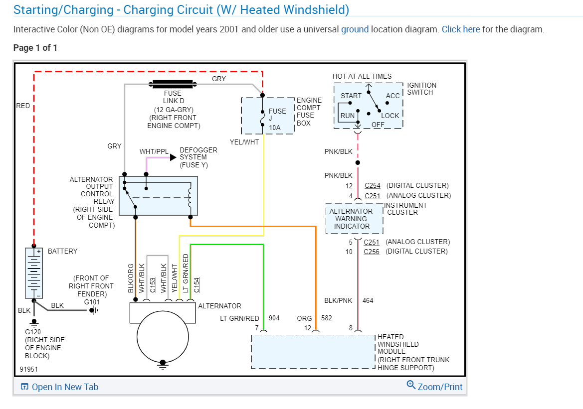
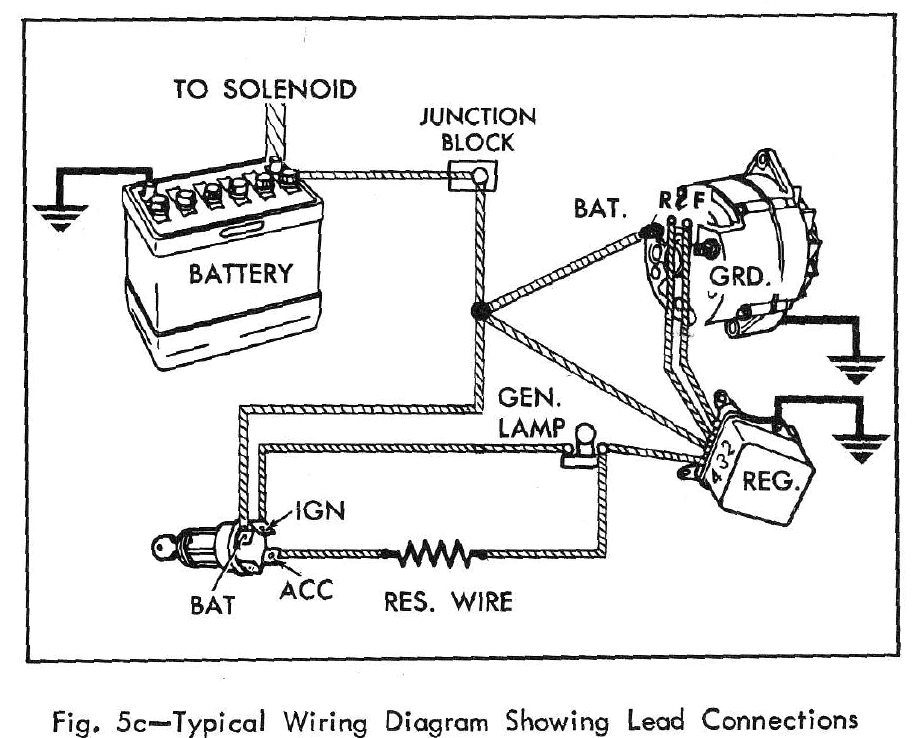
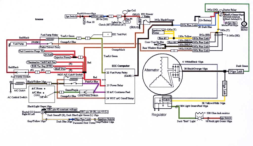
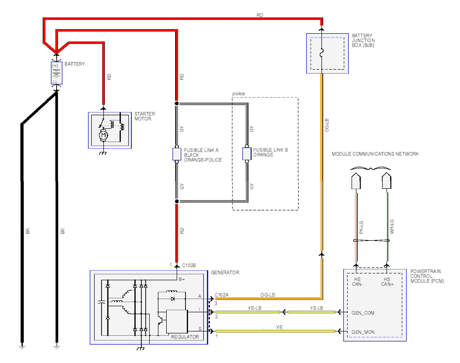
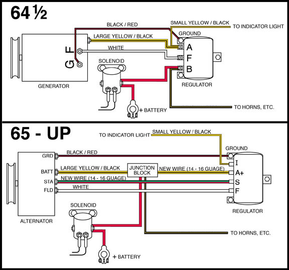
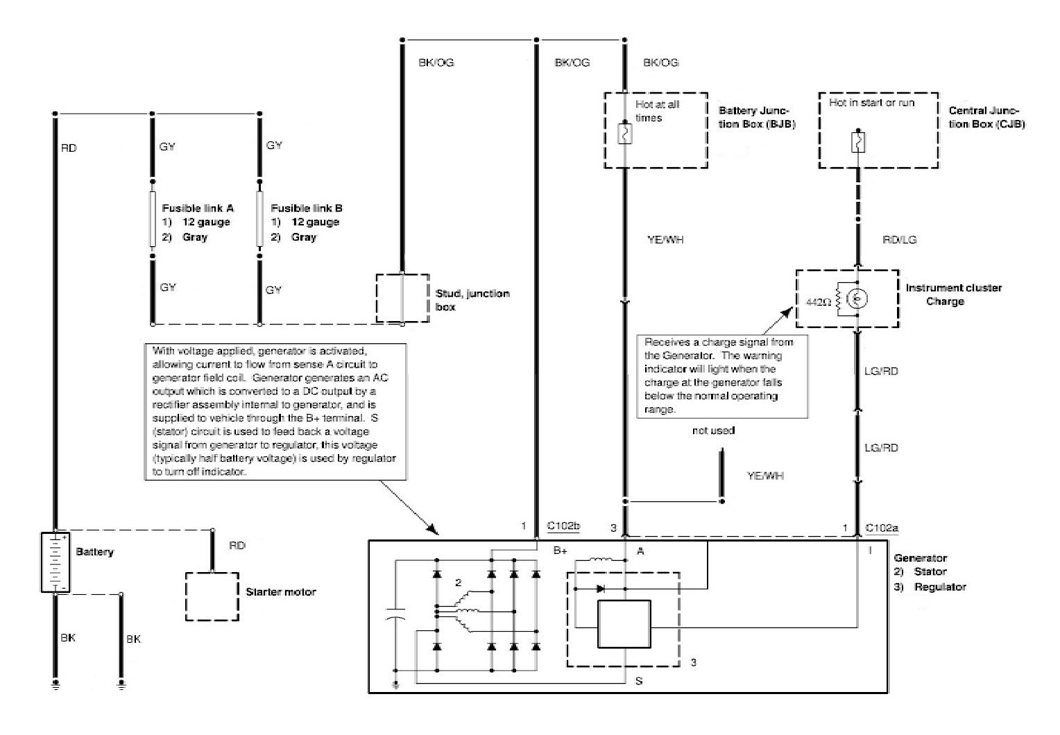
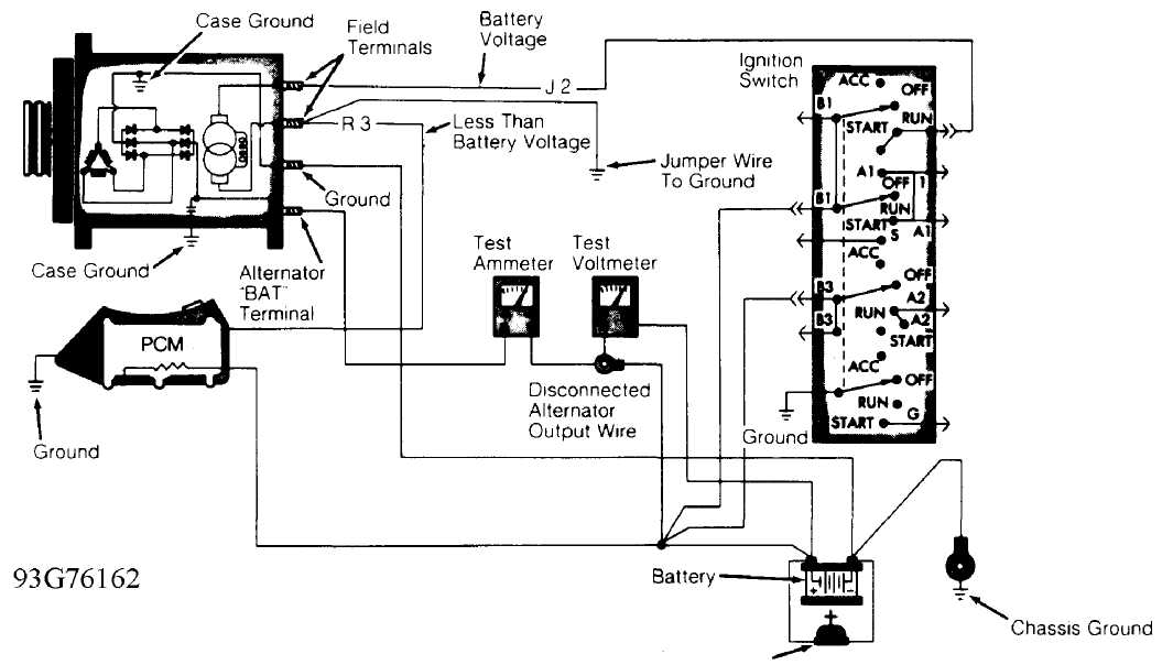
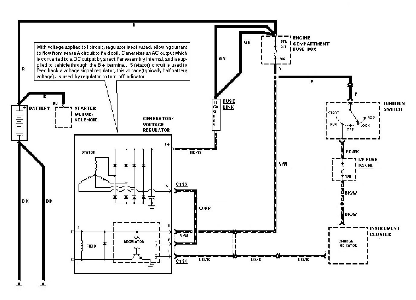
Below are wiring diagrams of the charging system in ford crown victorias This is the wiring diagram of the charging system used in the crownvics All of these cars have a 3G series alternator Here are the two regulator related wiring connectors for the cars The stator circuit is bridged externally to the regulator on the 9297 cars rather than internally. Charging System Overview and Conversion MOPAR CHARGING SYSTEM PRE1970 Diagram #1 shows the basics of the early alternator / voltage regulator design There are 2 brushes in the alternator, each one has a field terminal, one is labeled "FLD", the other is labeled "GND" The GND brush is grounded with the brush mounting screw. Charging System & Wiring DiagramAmazon Printed Bookshttps//wwwcreatespacecom/Amazon Kindle Editionhttp//wwwamazoncom/AutomotiveElectronicDiagn.
3 Wire Alternator Wiring Diagrams Google Search With Images New Wiring Diagram Car Charging System Alternator Click To Close Image Click And Drag To Move Use Arrow Keys For 3g Alternator Wiring Google Search Alternator Automotive Motorcycle Charging System Wiring Diagram 12v Wiring Schematic Inspirational Wiring Diagram For Leece Neville Alternator Diagrams Digramssample Diagramimages. Charging DIY Camper Batteries with an LiBIM The LiBIM (Lithium Ion Battery Isolation Manager) is a popular isolator designed specifically for use with Lithium BatteriesIt has higher voltage open/close parameters that allow the isolator to open and close at more appropriate times depending on if the alternator is charging the house battery bank or shore/solar is able to charge the starting. This page uses frames, but your browser doesn't support them.
Alt Wire Diagram Alternator Wiring And Out The Dash Warning Light – 12 Volt Alternator Wiring Diagram Wiring Diagram arrives with several easy to stick to Wiring Diagram Directions It’s supposed to assist all the typical user in developing a suitable method These guidelines will likely be easy to grasp and apply. Alternator Exciter Wiring Diagram – alternator exciter circuit diagram, alternator exciter wiring diagram, Every electrical arrangement is made up of various different pieces Each part ought to be placed and linked to other parts in particular way If not, the structure will not function as it ought to be. Feb 16, 15 3 wire alternator wiring diagrams Google Search.
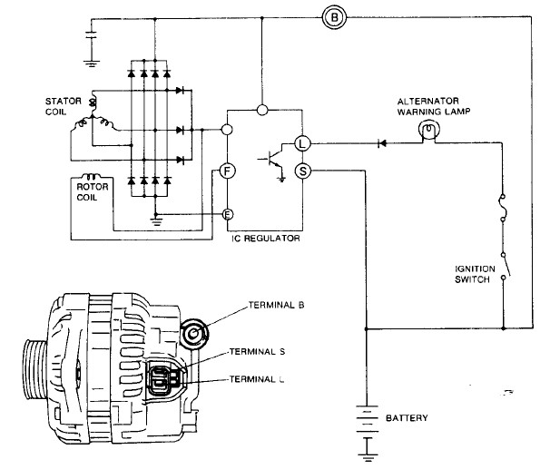
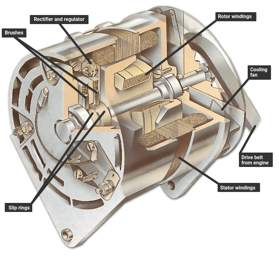
This car survived more than 50 years with the original charging system, but it's time for an upgrade We use a 1/2inch wrench to loosen the top retaining bolt See all 15 photos 3. Include the following items in a visual inspection of the charging system 1 Battery 2 Fusing 3 Alternator Drive Belt 4 Alternator Wiring 5 Noise 6 Charging Indicator Item 1 Battery Inspect the battery for the defects shown in this figure Fig 513 TL623f513c Charging System Visual Inspection. Figure 1 below is a block diagram or a functional diagram of an alternator and its connections to the remainder of the automobile electrical system This rotor spins past wire coils causing a magnetic field The other terminal is the exciter How alternator works diy voltage regulator.
Complete Charge System Wiring Diagrams 1985 & 1986 AMC Full Size Jeep (SJ) Charge and Headlight Diagrams (has their own pages) 1967 Plymouth Barracuda Typical of alternator systems using positive field regulation (single field wire at alternator) Wire colors will vary with year, make, model This Website. It wants to know if the charging voltage is reaching the fuse box. Mopar Charging Systems up to 1969 Diagram #1 shows the basics of the early alternator / voltage regulator (VR) design There are 2 brushes in the alternator, each one has a field terminal, one is labeled "FLD", the other is labeled "GND".
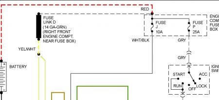
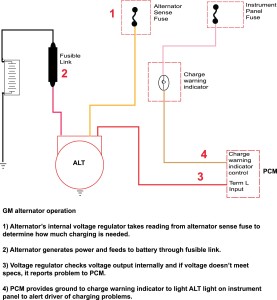
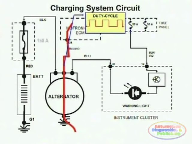
Kia Sorento Alternator Circuit Diagram Second Generation XM (1121) / Kia Sorento XM 1121 Service Manual / Engine Electrical System / Charging System / Alternator Circuit Diagram COM signal When controlling the voltage generated, the ECM sends the target voltage data to the alternator via a PWM signal(High voltage 4V or higher. In the BAT plug two wire version, the alternator checks system voltage via a “sense” fuse located in a vehicle fuse box The whole purpose is to check voltage away from the alternator itself The reason is pretty simple;. We show you how to upgrade the charging system in any car by installing a one wire alternator from Performance Distributors Only at wwwhotrodcom, the official website for Hot Rod Magazine.
Alt Wire Diagram Alternator Wiring And Out The Dash Warning Light – 12 Volt Alternator Wiring Diagram Wiring Diagram arrives with several easy to stick to Wiring Diagram Directions It’s supposed to assist all the typical user in developing a suitable method These guidelines will likely be easy to grasp and apply. Starting system circuit diagram https//youtube/iwu5ArpfouU. This car survived more than 50 years with the original charging system, but it's time for an upgrade We use a 1/2inch wrench to loosen the top retaining bolt See all 15 photos 3.
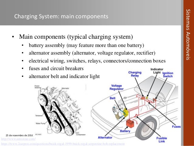
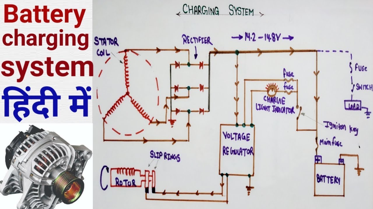
To give a visual indication of charging system operation Charging System Circuits The charging system consists of the following major circuits (Figure 84) • The field circuit,which delivers current to the AC generator (alternator) field • The output circuit, which sends voltage and current to the battery and other electrical components. Home › car alternator wiring diagram › car alternator wiring diagram pdf › charging system car alternator wiring diagram › race car alternator wiring diagram Alternator Wiring Diagram Car By blogger Thursday, February 6, 14 Edit A wiring diagram is a simplified traditional pictorial depiction of an electrical circuit It reveals. To give a visual indication of charging system operation Charging System Circuits The charging system consists of the following major circuits (Figure 84) • The field circuit,which delivers current to the AC generator (alternator) field • The output circuit, which sends voltage and current to the battery and other electrical components.
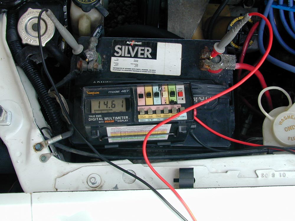
Example, Alternator SRIG is able of producing 150Amps The wiring (for maximal 5 metres) should be (150/3) 50mm² Be sure not to connect the Balmar alternator on the ground at any part of the system because it will be not ground isolated anymore!. Oct 16, 17 This Pin was discovered by Superior Automotive Technician Discover (and save!) your own Pins on. “An alternator with a higher amp output than stock requires a heavier charge wire (the wire that connects the alternator to the battery) because of the increased amperage” To evaluate your charging system, try this simple experiment.
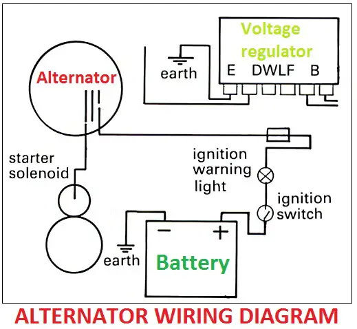
Home › car alternator wiring diagram › car alternator wiring diagram pdf › charging system car alternator wiring diagram › race car alternator wiring diagram Alternator Wiring Diagram Car By blogger Thursday, February 6, 14 Edit A wiring diagram is a simplified traditional pictorial depiction of an electrical circuit It reveals. Some modern alternators only have one wire as all the external functions are housed within the alternator and, as the alternator is fixed to the car engine, this completes the ground circuit However, the majority of alternators have three or four terminals which wires connect to Checking typical alternator wiring is a moderately easy task. Complete Charge System Wiring Diagrams 1985 & 1986 AMC Full Size Jeep (SJ) Charge and Headlight Diagrams (has their own pages) 1967 Plymouth Barracuda Typical of alternator systems using positive field regulation (single field wire at alternator) Wire colors will vary with year, make, model This Website.
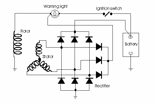
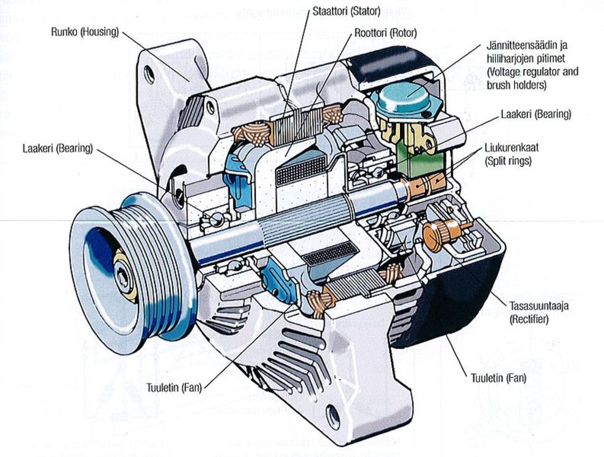
A shorted diode in the alternator can still allow a charging voltage of up to 133 volts, and can be detected by the battery going dead within several hours If this happens, charge the battery out of the car to confirm it is still good If you are still experiencing charging system issues, then the battery is suspect. In the BAT plug two wire version, the alternator checks system voltage via a “sense” fuse located in a vehicle fuse box The whole purpose is to check voltage away from the alternator itself The reason is pretty simple;. Here the basic internal circuit diagram of the car alternator and the wiring diagram of the alternator with battery is given below As you see there are the threephase alternator is used in the car The threephase alternator has two parts stator and rotor The stator contains the threephase armature winding and the rotor contains field winding.
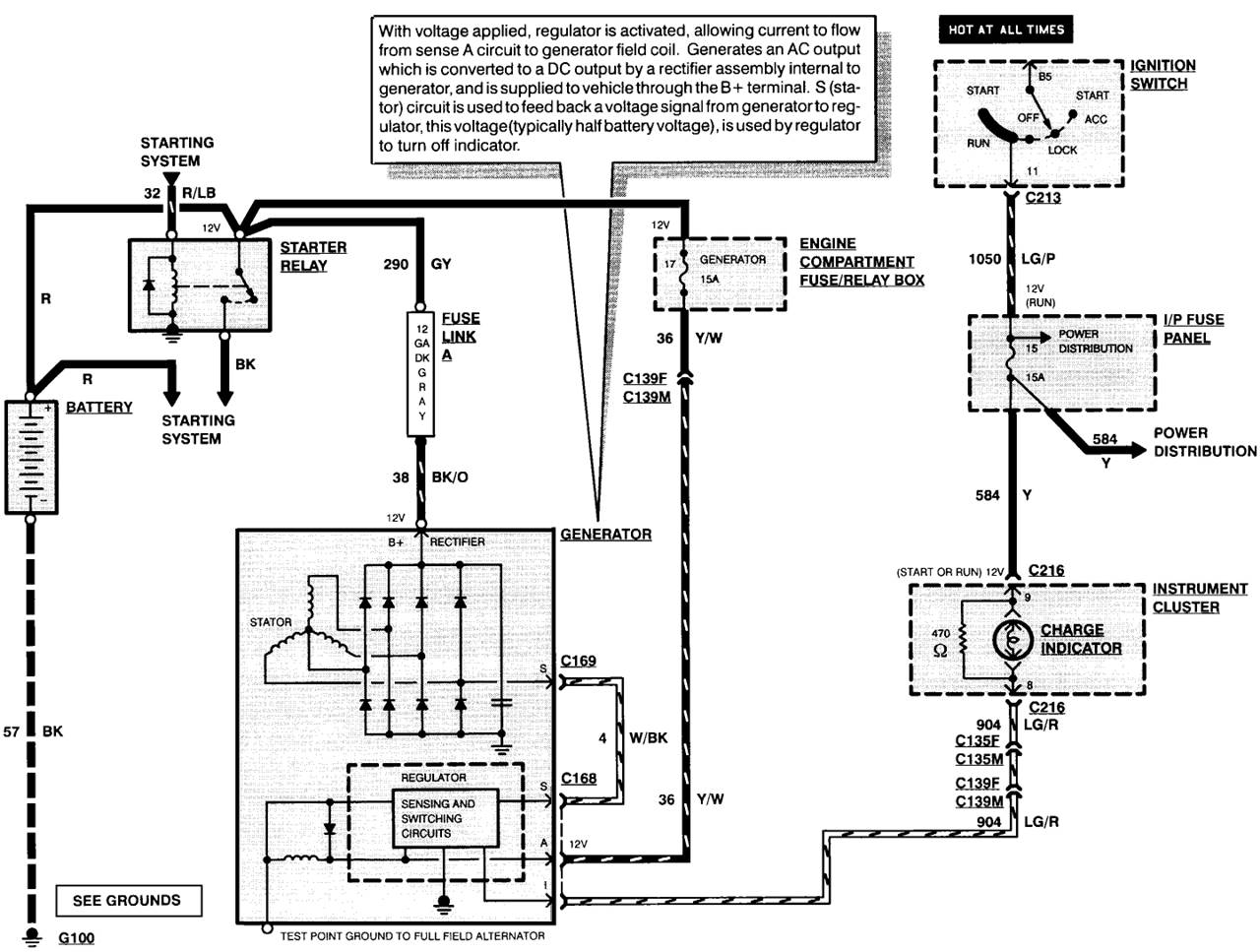
To give a visual indication of charging system operation Charging System Circuits The charging system consists of the following major circuits (Figure 84) • The field circuit,which delivers current to the AC generator (alternator) field • The output circuit, which sends voltage and current to the battery and other electrical components. Some modern alternators only have one wire as all the external functions are housed within the alternator and, as the alternator is fixed to the car engine, this completes the ground circuit However, the majority of alternators have three or four terminals which wires connect to Checking typical alternator wiring is a moderately easy task. Ford Alternator Wiring Diagram This is the diagram of every components in the alternator It is a diagram for the alternator in a Ford Focus (see also Ford Focus Repair Manual ), Ford Escort, Ford F100, Ford Taurus, Ford Mustang, Ford Model T, Ford GT40, Ford Thunderbird, Ford Shelby Cobra and other Ford cars that use the similar alternator.
My Lincoln Town Car Has A Charging Problem Though I Changed The, size 800 x 600 px, source wwwjustanswercom Here are a few of the leading drawings we obtain from different resources, we hope these images will certainly be useful to you, and also with any luck really pertinent to just what you desire regarding the Lincoln Alternator Wiring Diagram is. Charging System Briggs And Stratton Alternator Wiring Diagram Source i1wpcom READ 02 Yamaha R1 Wiring Diagram For Your Needs Before reading a schematic, get common and understand each of the symbols. New Wiring Diagram Car Charging SystemAllowed in order to our blog site, in this particular time period I’ll teach you regarding wiring diagram car charging systemAnd today, here is the initial impression alternator charging system wiring diagrams body of knowledge from wiring diagram car charging system, sourcecrownvicnet.
Charging System Overview and Conversion MOPAR CHARGING SYSTEM PRE1970 Diagram #1 shows the basics of the early alternator / voltage regulator design There are 2 brushes in the alternator, each one has a field terminal, one is labeled "FLD", the other is labeled "GND" The GND brush is grounded with the brush mounting screw. Troubleshooting the ignition warning light how a car works wiring diagram system fame locate ediliadesign it f150 alternator diagrams cute manage alcuoredeldiabete an full version hd quality tilediagram adim kdiagramxr interno5teatro gm square body 1973 1987 truck forum billavista com tech article by regulator diagrampress argiso battery for electric choke 250 cc piooner radios yenpancane. 12 Volt Alternator Wiring Schematic Collections Of Cessna Alternator Wiring Diagram New Aircraft Alternator Wiring Wiring Diagram 12 Volt Alternator Valid Obd1 Alternator Wiring Older Alternator Wiring Diagram with Internal Regulator New 12 Volt Electrical Wiring and Charging System Help – Wiring Diagram Collection.
Charging System Briggs And Stratton Alternator Wiring Diagram Source i1wpcom READ 02 Yamaha R1 Wiring Diagram For Your Needs Before reading a schematic, get common and understand each of the symbols. Alternator Wiring Problem Hi everyone, I have a '73, 304 CJ5, here is the problem I just got this cj a few weeks ago and recently noticed that the battery was not charging, Saved by El Prz. “An alternator with a higher amp output than stock requires a heavier charge wire (the wire that connects the alternator to the battery) because of the increased amperage” To evaluate your charging system, try this simple experiment.
Here the basic internal circuit diagram of the car alternator and the wiring diagram of the alternator with battery is given below As you see there are the threephase alternator is used in the car The threephase alternator has two parts stator and rotor The stator contains the threephase armature winding and the rotor contains field winding. Oct 16, 17 This Pin was discovered by Superior Automotive Technician Discover (and save!) your own Pins on.

Alternator Wiring Problem Jeepforum Com Alternator Car Alternator Forklift

Understanding The Leisure Battery Charging Circuit Caravan Chronicles
Alternator Wiring Diagram Changed Fuse J10 P25 As Suggested No
Charging System Car Alternator Wiring Diagram のギャラリー

Charging System Components Functions Mechanical And Automotive Engineering Books And News פייסבוק
Kia Optima Repair Procedures Charging System Engine Electrical System Kia Optima Tf 11 21 Service Manual

The Early Mopar 60 S And 70 S Wiring And How It Can Be Upgraded Bob S Garage Library
How Charging System Works 22re Yotatech Forums
Fork Lift Charging System Wiring Diagrams 1990 Dodge Dakota Wiring Harness For Wiring Diagram Schematics

Escape City Com View Topic 03 Charging System Diagram
Alternator Regulator Troubleshooting

27 Ford Alternator Wiring Diagram Internal Regulator Bookingritzcarlton Info Voltage Regulator Electrical Circuit Diagram Alternator

Charging System Definition Functions Parts Working Studentlesson

New Wiring Diagram Car Charging System Diagram Diagramtemplate Diagramsample Electrical Circuit Diagram Car Alternator Alternator

Campervan Split Charging A Helpful Illustrated Guide Vanlife Adventure
Me08
Http Www Autoshop101 Com Forms Elec05 Pdf
Fork Lift Charging System Wiring Diagrams 1990 Dodge Dakota Wiring Harness For Wiring Diagram Schematics

How To Wire A Gm Delco Type Cs130 Series Alternator
Thesamba Com Beetle Late Model Super 1968 Up View Topic Alternator Wiring
Testing Battery And Charging System

Prestolite Leece Neville
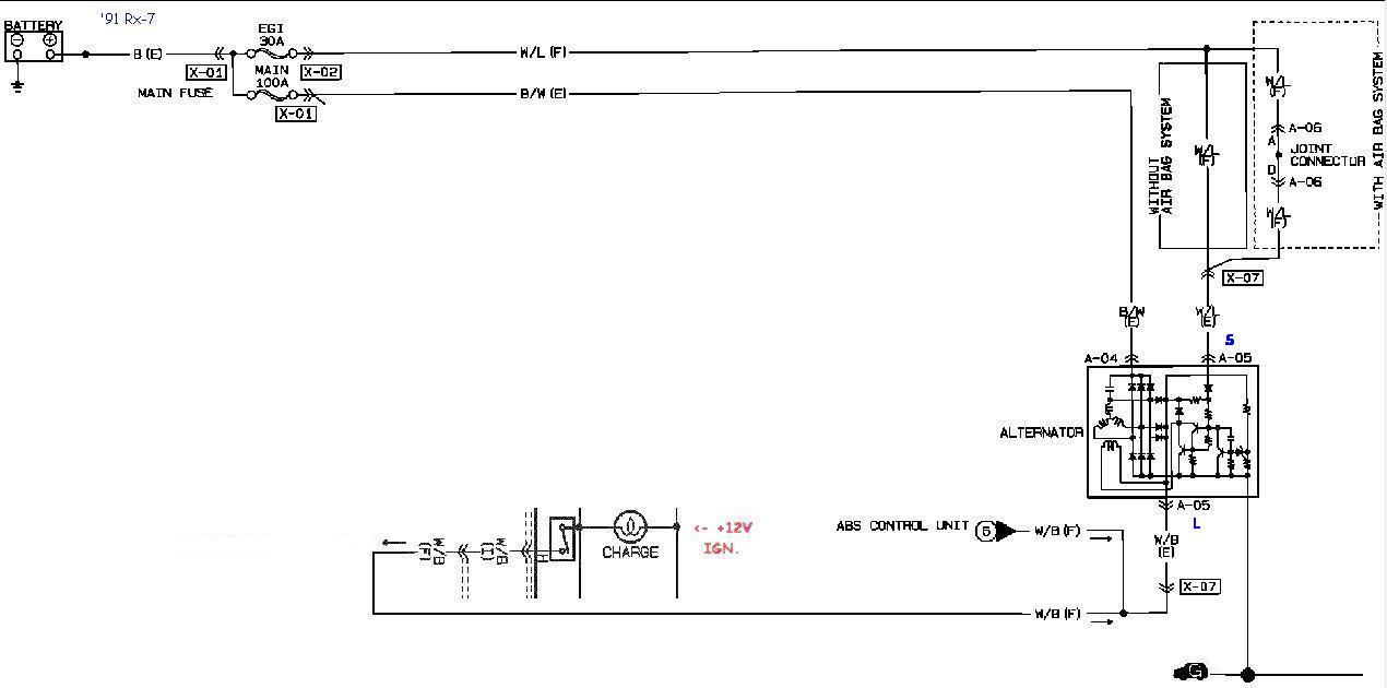
Rx 7 Alternator Cross Reference And Swap Chart

Kia Sedona Alternator Schematic Diagrams Charging System Engine Electrical System Kia Sedona Yp Service Manual
Mazda 323 Alternator Wiring Diagram Wiring Diagram Power Dana Power Dana Bookyourstudy Fr
Automotive Systems Course Module 07 Charging Systems For Road Veh

Alternator Charging System
Http Www Metroplexalternator Com Uploads 1 5 2 8 Charging System Theory Pdf
Q Tbn And9gcrx Nmuhpjbyltpbhydqauwibk4cy1hsvlmybydkdxszr1oysuu Usqp Cau
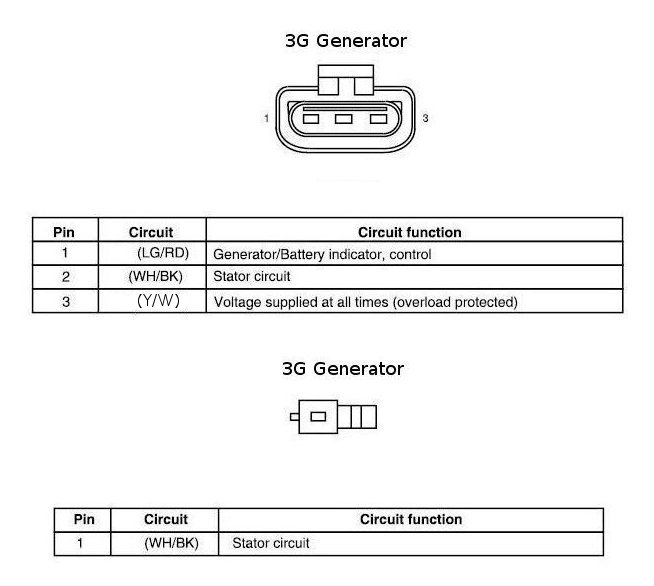
Ford Crown Victoria Alternator Wiring Diagrams
Testing Battery And Charging System
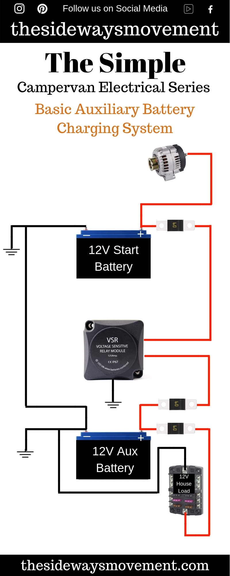
Auxiliary Battery Charging System Weekender Van Life
Ae86 16v Alternator Wiring Basics

How Does The Car Charging System Work Youtube
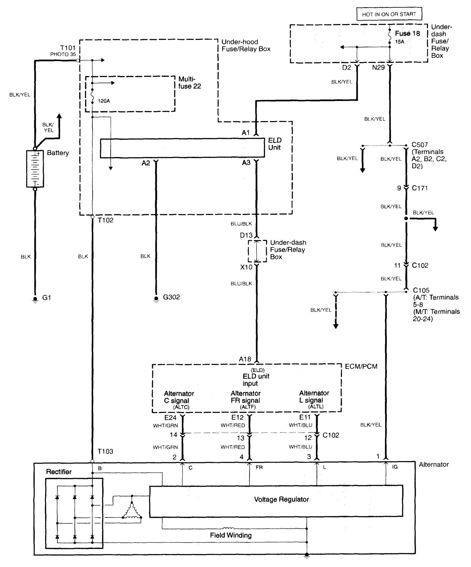
Acura Tl 06 Wiring Diagrams Charging System Carknowledge Info

Charging System Tests
Http Www Autoshop101 Com Forms Elec05 Pdf
Voltmeter Wiring Diagram Charging System In Isolator Schematic Begeboy Wiring Diagram Source

Diagram 1969 Plymouth Voltage Regulator Wiring Diagram Full Version Hd Quality Wiring Diagram Diagraminfoh Teatrosservanza It
Alternator Not Charging Honda Tech Honda Forum Discussion

New Wiring Diagram Car Charging System Diagram Diagramtemplate Diagramsample Alternator Electrical Circuit Diagram Electrical Diagram

Automotive Charging System Wiring Diagram Dakota Fuse Panel Diagram For Wiring Diagram Schematics

Alternator Upgrade Wiring Tips For Popular Gm Charging Systems

Charging System Definition Functions Parts Working Studentlesson
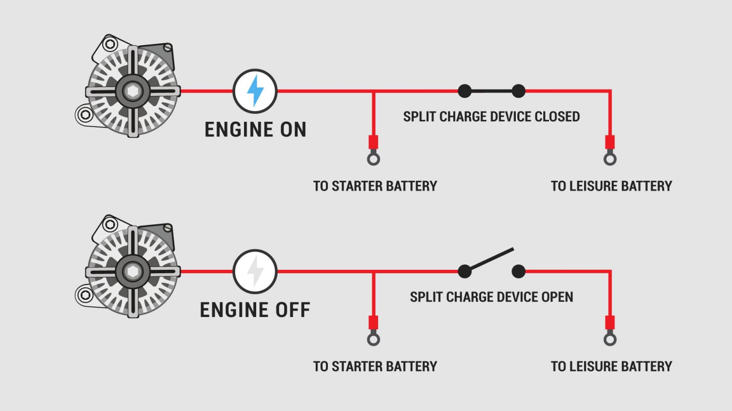
Campervan Split Charging A Helpful Illustrated Guide Vanlife Adventure

Wilbo666 Toyota Alternators

Chevy Alternator Wiring Diagram Alternator Electrical Circuit Diagram Car Alternator
Hyundai Tucson Alternator Schematic Diagrams Charging System
Engine Alternator Wiring Diagram 19 Softail Handlebar Wiring Diagram For Wiring Diagram Schematics
Automotive Charging System Wiring Diagram Zinc Process Flow Diagram For Wiring Diagram Schematics
Ford Crown Victoria Alternator Wiring Diagrams
1971 F100 Charging System Wiring Diagram Dodge Ram Dash Wiring Harness Pontloon Yenpancane Jeanjaures37 Fr

Charging System Tests
3
Alternator Wiring Diagram Changed Fuse J10 P25 As Suggested No
08 Chevy Alternator Wiring Diagram Wiring Diagram Electron Central B Electron Central B Navicharters It

Alternator Engine Diagram Wiring Diagram For Honeywell Motorised Valve Bege Wiring Diagram

Charging System Wiring Diagram Geo Ignition Switch Wiring Diagram Tomosa35 Jeep Wrangler Waystar Fr

Alternator Function And Alternator Wiring Diagram In Car Etechnog

Auto Mobile Alternator Wiring Diagram Rt3 Boss Plow Wiring Diagram For Wiring Diagram Schematics

Automotive Charging System Wiring Diagram Dakota Fuse Panel Diagram For Wiring Diagram Schematics
Mopar Charging Systems

Wiring Diagrams Toyota Sequoia 01 Repair Toyota Service Blog

Charging System Diagnoses

Toyota Alternator Wiring Diagram Pdf Wiring Diagram Load Dana B Load Dana B Bookyourstudy Fr
Alternator Voltage Regulator Wiring Ford Truck Enthusiasts Forums
Q Tbn And9gctj7lusl8m4w2zoue2w3set0pbge7ka Dy4cmuyvqr1 S8sg5tn Usqp Cau
How The Charging System Works How A Car Works
96 97 98 Mustang Altenator Starting And Charging System Wiring Diagram 97 Dodge Ram Headlight Wiring Diagram For Wiring Diagram Schematics
How To Wire dc From Caravan To Vehicle With Variable Voltage Alternator Redarc Electronics
Automotive Charging System Wiring Diagram Zinc Process Flow Diagram For Wiring Diagram Schematics
The Alternator

Lincoln Alternator Wiring Diagram
Alternator Circuit Diagram Battery Charging System Components Of Alternator In Hindi Youtube

Alternator Wiring Diagrams And Information Car Alternator Alternator Automotive Electrical

Design And Function Of Classic Car Voltage Regulators
04 F150 Charging System Wiring Diagram Wiring Diagram Solid Global A Solid Global A Navicharters It

Electrical Winding Wiring Diagrams Old Car Alternator Wiring Diagram

Ro 9731 Alternator Charging System Wiring Diagram On Charging System Wiring Schematic Wiring

Wiring Diagrams Toyota Sequoia 01 Repair Toyota Service Blog

Simple Alternator Wiring Diagram Alternator Car Alternator Automotive Repair

Toyota 3 Wire Alternator Wiring Diagram Dodge Pickup Trailer Wiring Diagram 7ways Yenpancane Jeanjaures37 Fr
Www Victronenergy Com Upload Documents Alternatorquickinstallationreference Pdf
Www Victronenergy Com Upload Documents Alternatorquickinstallationreference Pdf
Alternator Nippondenso 1993 Jeep Cherokee Xj Jeep Cherokee Online Manual Jeep
Hyundai Sonata Nf 05 13 Engine Electrical System
Catalog
Camaro Electrical
Troubleshooting Alternator And Charging System Problems Axleaddict A Community Of Car Lovers Enthusiasts And Mechanics Sharing Our Auto Advice
Http Www Autoshop101 Com Forms Elec05 Pdf

Smart Car Alternator Wiring Diagram 1998 Vw Cabrio Ac Wiring Doorchime Corolla Waystar Fr

3 Typical Car Starting System Diagram T X

Basic Dual Battery System

Mazda Alternator Wiring Wiring Diagram Load Meta Load Meta Bookyourstudy Fr
Ron Kilber S Logbook Aircraft Charging Systems
Q Tbn And9gctgxjs59lk Uyqief3x2morgsnpznprvt19 M Pp5f33pswn H Usqp Cau

Alternator Upgrade Wiring Tips For Popular Gm Charging Systems
Kia Rio Circuit Diagram Alternator Charging System Engine Electrical System Kia Rio Ub 12 21 Service Manual

Alternator Wiring

Wiring Diagram For Car Charging System Round 4 Pin Wiring Diagram Motorhome Pipiing Losdol2 Jeanjaures37 Fr

Prestolite Leece Neville
Kia K2700 Alternator Wiring Diagram
Charging System Wiring Diagram Youtube
Ford Crown Victoria Alternator Wiring Diagrams

Automotive Charging System Wiring Diagram Dakota Fuse Panel Diagram For Wiring Diagram Schematics


