Relief Valve In Hydraulic System
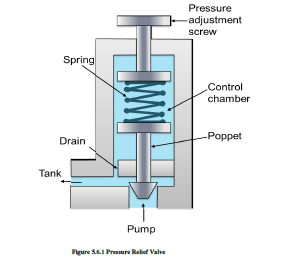
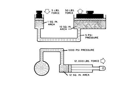
Hydraulic relief valves limit the maximum system pressure to protect system components The valves also limit the maximum output force of the hydraulic system Although they have a number of variations, all valves work by balancing the hydraulic force with an adjustable spring force Heat is created whenever the relief valve opens in response.

Relief valve in hydraulic system. When maintained properly, a pressure relief valve can stay in service for up to 30 years, and if you’ve been having your valves tested regularly, it’s likely that there’s something else in your system that’s to blame That said, pressure relief valves can and do fail, and it’s important to be able to recognize the signs in order to. In short, a relief valve is a hydraulic component designed to limit pressure in an entire system or subcircuit by diverting pressurized flow to the reservoir They are most often installed directly downstream of the pump to control system pressure, but can be used in other parts of the circuit to protect isolated components. Pressure relief valves are controlling hydraulic system operation pressure and keeping the working pressure in a normal stage The nominal hydraulic pressure and hydraulic valve side for hydraulic systems in machines or equipment should be took into consideration before design or repair hydraulic systems, in order to equip with correct pressure relief valve and right function to pressure relief valves, the result is to protect machine and control system pressure in normal level.
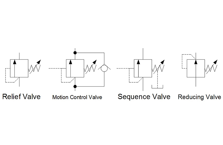
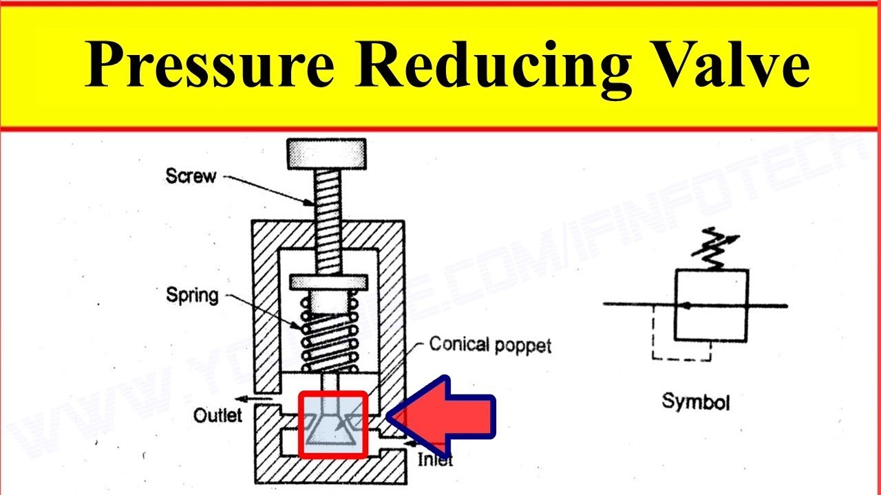
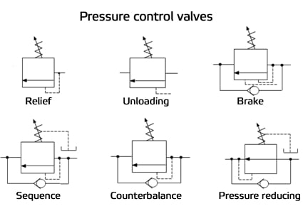
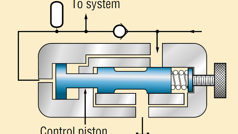
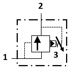
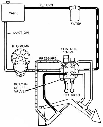
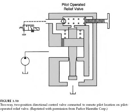
Design a valve specifically for your process media and set pressure Choose from a valve for air, inert gas, water, hydraulic oil, fuel oil, gasoline, or diesel fuel and a set pressure from 150 to 3, 300 psi These valves begin opening at the set pressure and fully open at about 10% over the set pressure They begin closing as pressure drops and fully close when the system pressure is restored. Pressure relief valves – Relief valve opens and bypasses fluid when pressure exceeds its setting These are used mostly in all circuits PressureReducing Valve – This type of valve (which is normally open) is used to maintain reduced pressures in specified locations of hydraulic systems. The relief valve in Figure 4 functions not only as an adjustable maximum pressure limiter but also, when vented, as a pump unloader It must be a 2stage valve, also called a pilotoperated relief, and must have an external vent port (sometimes called an RC, remote control port).
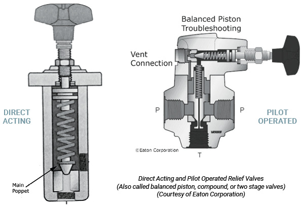
A relief valve or pressure relief valve (PRV) is a type of safety valve used to control or limit the pressure in a system;. Relief valves are used in hydraulic circuits to protect the downstream circuit from overpressurization by a pump They are factory set for a specified cracking pressure (ie set pressure), and are adjustable or available with tamper proof wire to inhibit field readjustment When inlet pressure is reduced to within 25% of set pressure, the relief valve reseals. Hydraulic Relief Valves (1) Simple Type Figure 52 shows a simpletype relief valve This valve is installed so that one port is connected to (2) Compound Type Figure 53 shows a compound type relief valve Passage C is used to keep the piston in hydraulic.
RVRVF Directacting relief valves are normally closed, pressurelimiting valves used to protect hydraulic systems from pressure spikes When the pressure at the inlet reaches the valve setting, the valve starts to open, throttling flow to limit the pressure rise Features • Factory set to your requested pressure relief • Inline valve. As described above, install the relief valve in the circuit with the pressure port connected to the pressure line and the tank port connected directly to the reservoir Ensure that the relief valve is adjusted to its lowest possible pressure setting Again, this avoids an unexpected condition when the hydraulic power is applied to the circuit with this newlyinstalled relief Once properly installed, set both the pump compensator and the newlyinstalled relief valve to their minimum settings. How do relief valves work?.
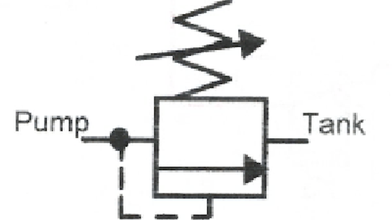
Pressure relief valves are used in hydraulic systems to limit the system pressure to a specific set level If this set level is reached, the pressure relief valve responds and feeds the excess flow from the system back to the tank Note the pressure relief valve is a normally closed pressure control valve Type of Pressure Control Valves. Pressure relief valve A pressure relief valve is a hydraulic component that provides safety to the hydraulic system from excessive pressureThis is normally closed but when the pressure in the hydraulic system increase beyond the set limit of a pressure relief valve, it opens the path and allows hydraulic oil to flow into the tankIn this way, it releases the excessive pressure from the. When your system cannot reach pressure, you’ll likely experience production slowdown, if not total downtime It’s good to know that checking your pressure relief valves can help you determine the problem System is Over Maximum Pressure Pressure relief valves and safety relief valves are what keep your facility safe In the event that your system builds up above the maximum pressure for safe functionality, safety relief valves open up to let off additional pressure, keeping your.
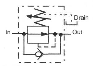
Pressure relief valves are controlling hydraulic system operation pressure and keeping the working pressure in a normal stage The nominal hydraulic pressure and hydraulic valve side for hydraulic systems in machines or equipment should be took into consideration before design or repair hydraulic systems, in order to equip with correct pressure relief valve and right function to pressure. Parker’s pressure relief valves are designed to limit the upstream pressure by opening at a preset value and discharging the medium Our range includes pressure relief valves in different mounting styles and for a variety of application areas industrial as well as mobile, for the use in hydraulic and pneumatic systems, for fluid and gas handling, process control and refrigeration. Check valves may also be used as a directional or pressure control in a hydraulic system In Figure 1, oil is flowing in from the left side port, through the check valve and out the right side port If the pressure equalizes or is higher in the right side port, the check valve will close and block flow in the opposite direction.
There are two types of valves, directional control valves and pressure relief valves Directional control valves manage the flow path of the fluid in the system Pressure relief valves protect the system plumbing and components against pressure overloads They also limit the output force exerted by rotary motors and cylinders. Our video shows you the cracking pressure, the reseating pressure and what you really need to know about how a hydraulic pressure relief valve worksRelief. It may help you discover a malfunctioning valve you wouldn't find otherwise, and will give you an idea of the valve's barsperturn ratio, which is a handy reference So, to resume whenever you come across a pressure relief valve in a malfunctioning hydraulic system, always check both its setting and adjustability.
Hydraulic system 71 includes a hydraulic pump 73, a hydraulic reservoir 75, a hydraulic actuator 77, a pressure relief valve 79, and a heat exchanger 81 Hydraulic system 71 also includes a solenoid operated bypass valve for isolating hydraulic system 71 by connecting the inlet port to the outlet port. A relief valve or pressure relief valve (PRV) is a type of safety valve used to control or limit the pressure in a system;. Hydraulic Bypass Relief Valves help limit your hydraulic systems pressure to whatever set level you desire Once the set level is reached, the relief valve then feeds the excess flow from your hydraulic system back to the tank Anderson Process now offers Fulflo hydraulic bypass relief valves in a variety of different sizes, material and.
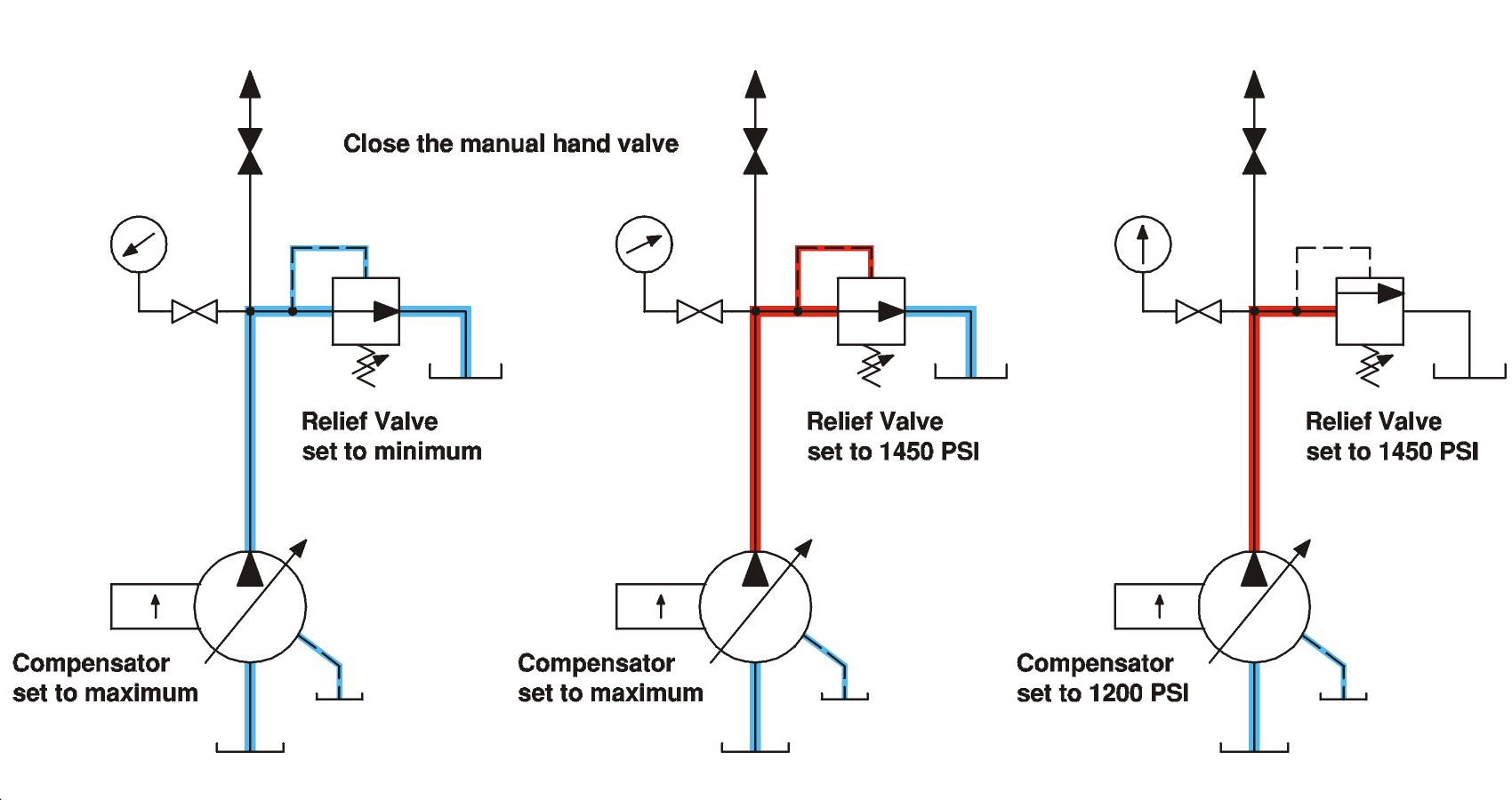
Pressure relief valves are used in hydraulic systems to limit the system pressure to a specific set level If this set level is reached, the pressure relief valve responds and feeds the excess flow from the system back to the tank Note the pressure relief valve is a normally closed pressure control valve Type of Pressure Control Valves. In order for the hydraulic system to run as efficiently as possible, two critical settings are the pump compensator and the system relief valve Of all of the adjustments that we find made incorrectly, these two are the most common Often the pressure setting of the pump compensator has been increased, sometimes above the setting of the relief valve. Pressure Relief Valve In some systems, especially those utilising a fixed displacement pump, pressure relief valves are incorporated to ensure that nominal system pressure is not exceeded If system pressure becomes too high, the relief valve opens and fluid is returned to the reservoir Hydraulic Fuses.
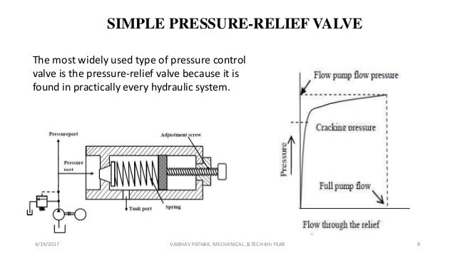
What Are Hydraulic Pressure Relief Valves And How To Test 1 Hydraulic power source It is required that the flow rate be smoothly adjustable throughout the test range, which is 2 The pressure relief valve in the system is used for safety protection only The pressure set value must be higher. Pressure might otherwise build up and create a process upset, instrument or equipment failure, or fire The pressure is relieved by allowing the pressurized fluid to flow from an auxiliary passage out of the system. The pressure relief valve is used in almost every hydraulic system The function of the relief valve is to limit the maximum pressure that can exist in a system Under ideal conditions, the relief valve should provide alternative flow path to tank for the fluid while keeping the system pressure constant.
A relief system is an emergency system for discharging gas during abnormal conditions, by manual or controlled means or by an automatic pressure relief valve from a pressurized vessel or piping system, to the atmosphere to relieve pressures in excess of the maximum allowable working pressure (MAWP). Hydraulic relief valves limit the maximum system pressure to protect system components The valves also limit the maximum output force of the hydraulic system Although they have a number of variations, all valves work by balancing the hydraulic force with an adjustable spring force. The relief valve is fully open or vented because the control piston pushes the pilot control piston off its seat Without a control piston, relief valves relieve excess pump flow at set pressure, generating a lot of heat This unloading relief valve has a preset differential of 15% between unloading and reloading the pump Fig 19.
DRV Direct Acting Relief Valve COMPATIBLE WITH MOST FLUIDS ADJUSTABLE SENSING PRESSURE FACTORY SET PER CUSTOMER REQUEST PRESSURES FROM 100PSI TO 60,000PSI MODELS SUITABLE FOR BOTH LIQUID OR GAS SC Hydraulic Engineering direct acting relief valves are available in 1/4" NPT and 9/1618 60 cone high pressure fitting for relieving pressures from 100 to 60,000 psi. Find out by watching this Live Schematic screencast, then si. Gradual or sudden loss of hydraulic pressure or flow resulting in a loss of power is common in hydraulic system failure Trouble, problem with hydraulic system OVERHEATING OF OIL IN SYSTEM Oil passing thru relief valve for excessive time Return control valve to neutral when not in use Incorrect oil, low oil, dirty oil Use recommended.
What's the difference between cracking pressure and setting pressure?. When we talk about hydraulic pressure relief valve systems, we’re talking about the systems that use a hand pump to apply the lifting force Operators use the hand pump to slowly increase pressure on the safety valve, and once the pressure builds up to the setpoint, the valve releases Electronic systems function similarly, but use a softwarecontrolled electric motor, rather than hydraulics, to build up pressure and take a reading once that pressure relief valve begins to open. Step 2 Pump and Relief Valve If cleaning the pump inlet strainer does not correct the trouble, isolate the pump and relief valve from the rest of the system by disconnecting the plumbing at Point B and capping both ends of the disconnected lines This deadheads the pump into the relief valve.
As a system relief valve, it regulates maximum working pressure in hydraulic systems and protects the hydraulic system or machine structure Maximum flow through relief valve 1325 L/min (35 gal/min) Relief valve setting range 69 to 241 bar (1,000 to 3,500 psi) Housing rated pressure 345 bar (5,000 psi). (12) 12 product ratings For Ford 8N 9N 2N Hydraulic Relief Valve For Massey TO30 TO M91 8N638. Every hydraulic system should have at least one, if not two relief valves One main relief valve and one backup relief valve The main relief will ensure the system does not work above a certain pressure The backup relief valve will kickin should the main relief fail and is usually set 0300 psi higher than the main relief.
Pressure might otherwise build up and create a process upset, instrument or equipment failure, or fire The pressure is relieved by allowing the pressurized fluid to flow from an auxiliary passage out of the system The relief valve is designed or set to open at a. RVRVF Directacting relief valves are normally closed, pressurelimiting valves used to protect hydraulic systems from pressure spikes When the pressure at the inlet reaches the valve setting, the valve starts to open, throttling flow to limit the pressure rise Features • Factory set to your requested pressure relief • Inline valve will operate when mounted in any position in your hydraulic system. Logic valves have distinct advantages, primarily because they are mounted in a manifold This enables them to cope with high pressures better than conventional hydraulic plumbing Over time, hydraulic systems are being operated at higher and higher pressures This allows the use of smaller actuators, making the systems much more efficient.
A relief system is an emergency system for discharging gas during abnormal conditions, by manual or controlled means or by an automatic pressure relief valve from a pressurized vessel or piping system, to the atmosphere to relieve pressures in excess of the maximum allowable working pressure (MAWP). In short, a relief valve is a hydraulic component designed to limit pressure in an entire system or subcircuit by diverting pressurized flow to the reservoir They are most often installed directly downstream of the pump to control system pressure, but can be used in other parts of the circuit to protect isolated components. Pressure relief valves cannot be used as pressure regulators in large hydraulic systems that depend on enginedriven pumps for the primary source of pressure because the pump is constantly under load and the energy expended in holding the pressure relief valve off its seat is changed into heat.
In short, a relief valve is a hydraulic component designed to limit pressure in an entire system or subcircuit by diverting pressurized flow to the reservoir They are most often installed directly downstream of the pump to control system pressure, but can be used in other parts of the circuit to protect isolated components. A B2B hydraulic component manufacturer specializing in standard and customized, engineered to order, hydraulic cylinders, valves, pumps, motors and miscellaneous components. (12) 12 product ratings For Ford 8N 9N 2N Hydraulic Relief Valve For Massey TO30 TO M91 8N638.
Once properly installed, set both the pump compensator and the newlyinstalled relief valve to their minimum settings Start the hydraulic pump and begin to turn the system relief valve to nearly the maximum adjustment position Now begin to adjust the pump pressure compensator to a setting about 0 PSI above the final desired system pressure. Model system relief valve The model is a top assembly body and relief valve It uses different relief cartridges or a plug, with options for fixed pilotoperated or fixed directacting cartridges As a system relief valve, it regulates maximum working pressure in hydraulic systems and protects the hydraulic system or machine structure. Relief valves are used in hydraulic circuits to protect the downstream circuit from overpressurization by a pump They are factory set for a specified cracking pressure (ie set pressure), and are adjustable or are available with tamper proof wire to inhibit field readjustment.
Hydraulic Relief Valves Northern Tool offers prograde, adjustable hydraulic relief valves that come ready to install and protect your hydraulic system Our relief valves will not jam, seize, or lock They are made with industriallevel materials that can withstand any work environment or hydraulic system. Relief valves are designed to open at a preset pressure (or temperature) level and relieve the system when it has exceeded the desired level The valve's relief of elevated liquid, gas, or steam pressures prevents damage to the system We offer a wide selection of relief valves for any application. The pressurerelief valve provides protection against any overloads experienced by the actuators in the hydraulic system Of course, a relief valve is not needed if a pressurecompensated vane pump is used Obviously one important function of a pressurerelief valve is to limit the force or torque produced by hydraulic cylinders or motors.
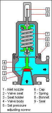
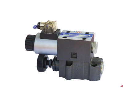
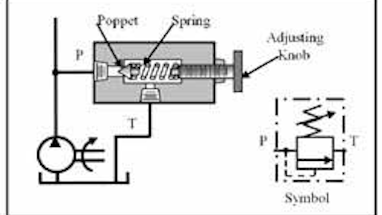
Parker’s pressure relief valves are designed to limit the upstream pressure by opening at a preset value and discharging the medium Our range includes pressure relief valves in different mounting styles and for a variety of application areas industrial as well as mobile, for the use in hydraulic and pneumatic systems, for fluid and gas handling, process control and refrigeration. If possible, disconnect the tank return line from the relief valve at Point C Attach a short length of hose to the relief valve outlet Hold the open end of this hose over the tank filler opening where the rate of oil flow can be observed Start the pump and run the relief valve adjustment up and down while observing the relief valve discharge flow. Pressure relief valve will have two sections ie Body section and pilot valve section Body section of relief valve will have a piston which will be retained to its position or seat due to the action of spring force Pilot valve section will control the piston movement with the help of hydraulic force.
Get hydraulic parts here http//amznto/1XhUWpQToday we are setting the pressure on my hydraulic power pack My hydraulic cylinder is rated for 2500 psi max. Hydraulic Valve Division offers both precise and robust pressure relief valves Parker offers a wide array of inline and subplate pressure relief valves for both manual and proportional application requirements. Hydraulic pressure relief valve testing systems are notoriously heavy In order for the hydraulic system to function properly, the system needs a long length of bulky hydraulic hose This increases the size of the system overall and makes it difficult to carry around, especially in tightquartered facilities where pressure relief valves can be.
A B2B hydraulic component manufacturer specializing in standard and customized, engineered to order, hydraulic cylinders, valves, pumps, motors and miscellaneous components. Chief SL Series High Pressure Relief Valve 16 GPM, PSI Adjustable Range and 1500 PSI Relief Setting with 1/2 NPTF Port Size 41 out of 5 stars 2 $4943 $ 49 43.

Ppt Hydraulic Valves Powerpoint Presentation Free Download Id

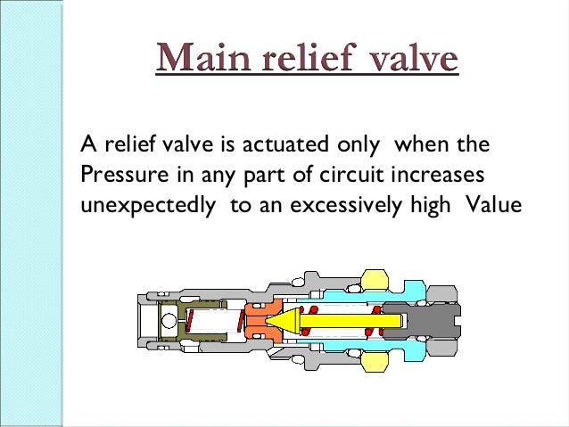
How Main Relief Valve Works Youtube
Thermal Relief Valve
Relief Valve In Hydraulic System のギャラリー
Hydraulic Systems Pressure Relief Valves

Pilot Operated Pressure Relief Valves

99 Hydraulic System Pressure Relief Valve

Pressure Control Upstream And Downstream

Engineering Essentials Pressure Control Valves Hydraulics Pneumatics
What Is A Pressure Reducing Valve And How Is It Used In Hydraulics Smith S Hydraulic

Hydraulic Pressure Relief Valve Hydraulic Relief Valve Mech Valve

Control Components In A Hydraulic System Pressure Control Valves Hydraulics And Pneumatics
Hydraulic Pilot Operated Relief Valve Hydraulic Valve

Pressure Relief Valves Pressure Control Valves

Hydraulic Power Systems Valves Part Three

完整ppt讲解 各种液压阀的工作原理与计算选择 Ihydrostatics静液压
Crossover Relief Valves Related Fluid Power
Hydraulic Symbology 3 Pressure Valves

Difference Between Pressure Reducing Valve And Pressure Relief Valve Engineering Made Easy Relief Valve Valve Hydraulic Systems
Basic Hydraulic Theory Cross Mfg

Pressure Relief Valve Training
Relief Valve Wikipedia
Q Tbn And9gcrnne1 Iseawvdnarue9f0mgteoqebjmtbud1cyqgmkc4tniyge Usqp Cau

Control Engineering Benefits Of Multiple Relief Valves In A Hydraulic System
Book 2 Chapter 18 Pressure Relief Valves Hydraulics Pneumatics
Setting The Pump Compensator And System Relief Valve Gpm Hydraulic Consulting Inc

Schematic Diagram Of The Hydraulic System 1 Reservoir 2 Pump 3 Download Scientific Diagram

Hydraulic Relief Valves Northern Tool
Pressure Reducing Valve Working Video In Hydraulic System Youtube

Basic Hydraulic Systems

The Pressure Relief Valve In The Motor Circuit
5 3 Pressure Reducing Valves Hydraulics And Electrical Control Of Hydraulic Systems

Power Control Unit Designaerospace Llc
Pilot Operated Pressure Relief Valves Hanshang Hydraulic Valves
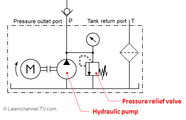
Pressure Relief Valve Learnchannel Tv Com
Remote Control Pressure Relief Valves Manufacturer Supplier Factory Exporter Of China
The Lowdown On Pressure Reducing Valves
Q Tbn And9gctmdtfiaqftif8fvfyavoite6iwxsof7wiwkckd6oevdocd2ib Usqp Cau

Hydraulic Pressure Relief Valve Hydraulic Relief Valve Mech Valve

Hydraulic Pressure Relief Valve Is Assembled And Tested Via Emap Promess Inc

Aircraft Hydraulic System Valves Aircraft Systems

Hydraulic Pressure Reducing Valves Hydraulic Valve
Hydraulic System And Its Components Ispatguru
Relief Valves
Control Valve Use In Hydraulic System Of Heavyt Equipment

Hydraulic Power Systems Valves Part Three
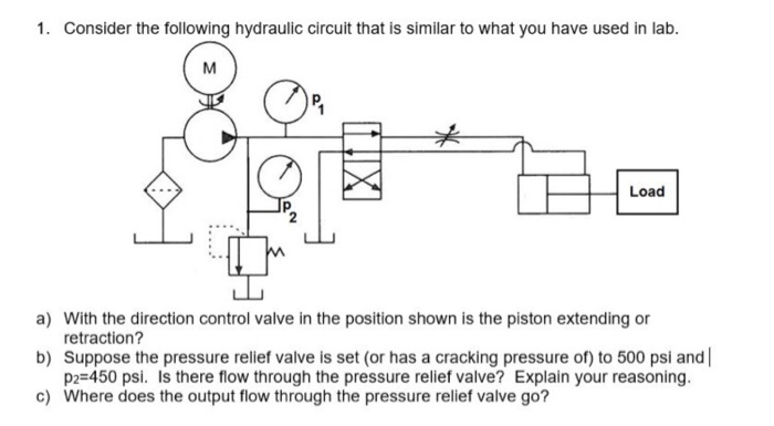
Solved 1 Consider The Following Hydraulic Circuit That I Chegg Com

Eaton Vickers Kcg 3 Proportional Valves Pressure Relief Valves

Minimizing Shock In Hydraulic Systems Womack Machine Supply Company
Pressure Reducing Valve And Pressure Relief Valve Stuffworking Com

Hydraulic Pressure Relief Valve Operation Uses And Types Youtube
In Line Relief Valve Buyers Products
Reading Fluids Circuit Diagrams Hydraulic Pneumatic Symbols
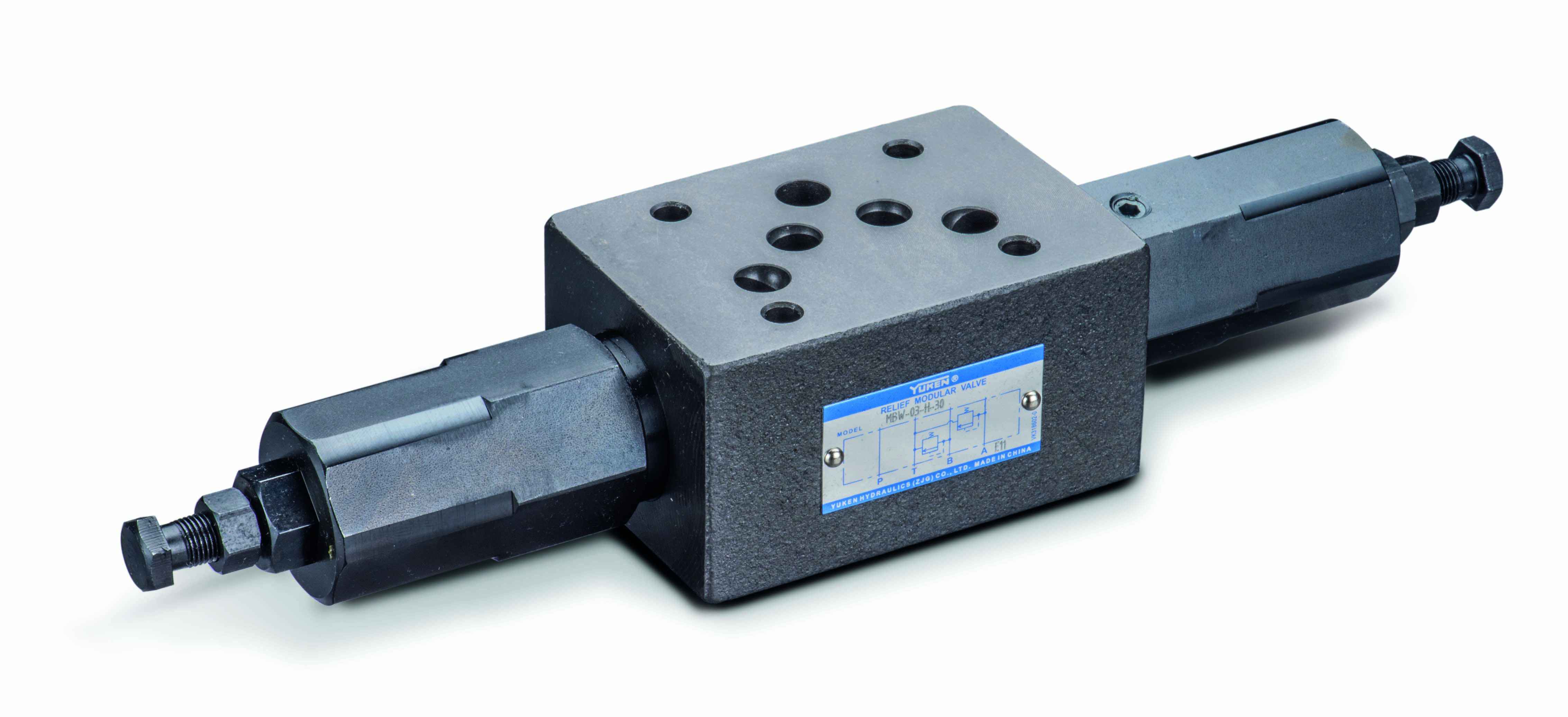
Cetop 5 Ng10 Pressure Relief Valve Yuken Hydraulic Specialists

Hydraulic Schematic Troubleshooting

Hydraulic Pressure Relief Valves In Hindi Youtube
Q Tbn And9gcrm M4sbl5oakzg9es Bn40v0wgg1 V5aqbd03yu Dqvuuz4ln Usqp Cau

Relief Valves Why One Is Not Enough Crossco

Hydraulic Relief Valves Northern Tool

A Pressure Relief Valve Finotek
Pressure Relief Valve Pneumatics Hydraulic
Q Tbn And9gcqtun4kzwdkqxe4loxy5d7 M8df Sqvlrurmamridk Ltubrbnd Usqp Cau

Hydraulic Pressure Reducing Valves Hydraulic Valve
Understanding Pressure Control Valves Hydraulics Pneumatics
Common Fluids Valves Explained Cartridge Pressure Relief Valve

Relief Hydraulic Pressure Relief Valve Water Piping System Mech Valve

Hydraulic Power Systems Valves Part Three

Hydraulic Pressure Reducing Valve Hydraulic Pressure Regulator Valve

Aircraft Hydraulic System Valves Aircraft Systems
A Schematic Representation Of A Pressure Relief Valve Connected To A Download Scientific Diagram

Differential Relief Valves Related Fluid Power Hydraulic Systems Relief Valve Control Valves

A View Of The Hydraulic System 1 Pump 2 Pressure Relief Valve 3 Download Scientific Diagram
Pressure Relief Valve Learnchannel Tv Com

Hydraulic Symbology 2 Stacked And Piloted Industrial Valves

Hydraulic Symbology 3 Pressure Valves

Difference Between Pressure Reducing Valve And Pressure Relief Valve Mechanical Engineering Concepts And Principles

Hydraulic Accessories Pressure Relief Valve Parker Na

Pressure Valve Schematic Diagram Electrical Wiring Diagrams

Pressure Control Valves Hydraulic Direct Acting Relief Valve Working Principle Hydraulic Schematic Troubleshooting
Hydraulics Systems Diagrams And Formulas Cross Mfg

Main Relief Valve Hydraulic Excavator Komatsu Pc100 2 Hydraulic System 777parts
Assemble A Hydraulic Pilot Operated Pressure Relief Valve Fluid Power Journal

A Guide To Common Hydraulic Symbols Engineeringclicks

Troubleshooting Tips For Hydraulic Systems Womack Machine Supply Company

3 Ways To Reduce Hydraulic Shock

Hydraulic Equipment Slowdown Nailing Internal Leakage
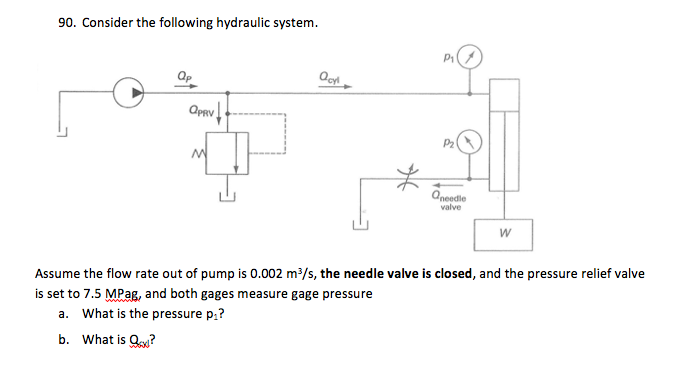
Solved 90 Consider The Following Hydraulic System Op Op Chegg Com
5 3 Pressure Reducing Valves Hydraulics And Electrical Control Of Hydraulic Systems

Understanding Pressure Control Valves Hydraulics Pneumatics
Chapter 9 Relief And Unloading Pressure Controls Hydraulics Pneumatics

Aircraft Hydraulic Systems

Hydraulic Relief Valve All Industrial Manufacturers

Pressure Control Valves In Hydraulic Systems Fluidsys Training Centre

Laboratory Hydraulic System 1 Gear Pump 2 Directional Valve 3 Download Scientific Diagram
Open And Closed Center Hydraulic Systems

What Are Hydraulic Pressure Relief Valves And How To Test Finotek
Hydraulic Pressure Valves
Pilot Operated Relief Valves Hydraulic Circuits Hydraulic Valve

Hydraulic Relief Valves Hydraulic Valve

Book 2 Chapter 18 Pressure Relief Valves Hydraulics Pneumatics

Fluid Power Safety Institute Flow Meter With Integral Safety Relief Valve

Hydraulic Control An Overview Sciencedirect Topics

Hydraulic Pressure Control Modern Industrial Hydraulics
Relief Valve Wikipedia

Hydraulic Vs Electronic Pressure Relief Valve Testing System Accutest Systems


